
 WhatsApp: +86 16626708626
 Email:
  Phone: +86 16626708626
Description
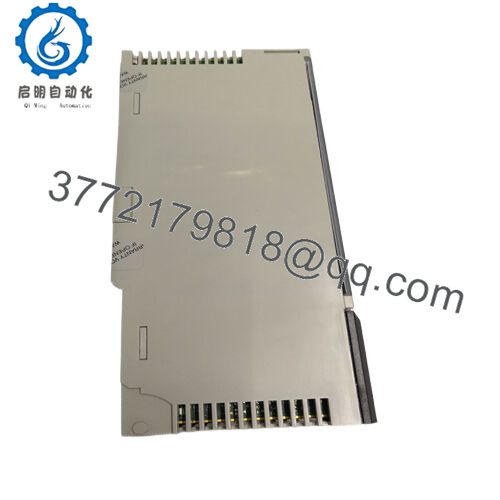
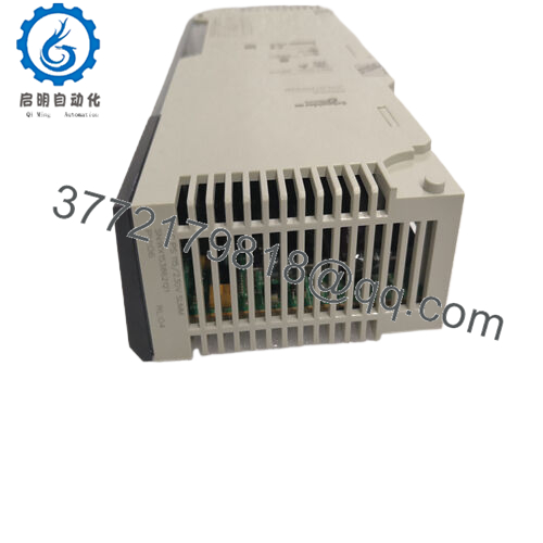
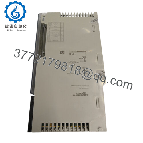
Product Model: 140CPS11420
- Product Brand: Schneider Electric
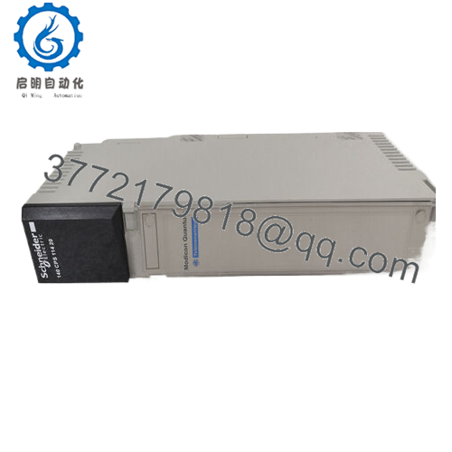
- Product Series: Modicon Quantum
- Product Features:
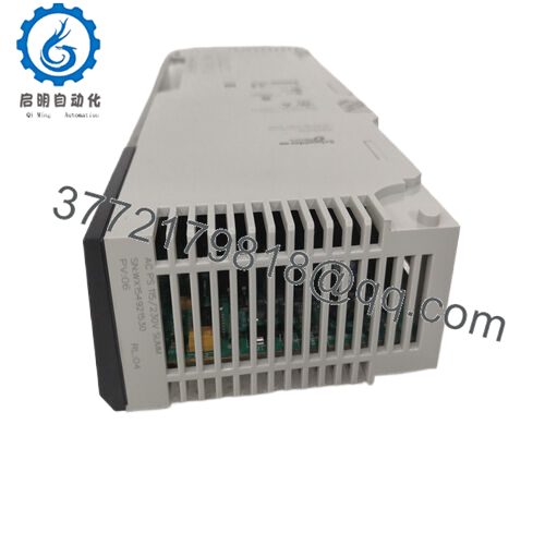
• AC input range 115 / 230 VAC, summable or standalone mode
• Output 5.1 V DC up to 11 A (standalone) or 20 A (summable)
• Internal protection (overvoltage, overload), LED status indicator, alarm contact
• Rugged design: suitable for 0–60 °C, altitude to 5000 m, CE/UL/CSA compliance

- 140CPS11420

Product Role & System Fit
In any Modicon Quantum control rack, the 140CPS11420 serves as the core power backbone. Without stable, reliable power, the entire automation system would falter. This module converts AC mains (115/230 V) into regulated DC voltage that drives logic modules, communication cards, I/O backplanes, and signal modules. Because it supports both “standalone” and “summable” use modes, the 140CPS11420 can act alone in small systems or be paralleled with other supplies in redundancy or load-sharing configurations.
When building or expanding a Quantum rack, integrators often reserve one slot (or two) for these power modules. The power supply sits adjacent to the CPU and I/O sections, supplying both the backbone bus and the module rails. Its summable mode allows multiple units to be tied together so that if one fails or drops current, the others pick up the slack.
Because Quantum systems are modular, replacing or upgrading the 140CPS11420 doesn’t force you to redesign logic. It fits the standard module format, occupying typical power slots in the chassis. Many engineers use it interchangeably with its “C” variant (140CPS11420C), though life-cycle statuses may differ.
When modernizing older installations, the 140CPS11420 often retains relevance because its output spec (5.1 V DC) matches many vintage modules. It functions as a “drop-in” replacement in many cases, so long as the AC input and physical constraints are met.
One subtle point: in automatic systems with battery backup or UPS, the input current and inrush spec of 140CPS11420 must be considered during power-up to avoid nuisance tripping of upstream protections. The datasheet reports inrush currents of 19 A at 230 V and 38 A at 115 V. In practice, large systems often stagger power supply module ramp times or use soft-start circuits.
Applications & Industry Context
I’ve seen 140CPS11420 modules deployed in a wide variety of industrial settings: water treatment SCADA systems, petrochemical control panels, manufacturing lines with strict uptime demands, and even aerospace testing cells. In any context where reliability counts, power supply modules matter.
Take a chemical processing plant. The control room’s Quantum rack carries the CPUs, analog input modules, network converters, and interface cards. In such an environment, ambient heat, dust, and occasional line fluctuations are constant threats. The 140CPS11420, with internal protection and rugged design, provides stable DC to sustain the entire logic backbone.
In packaging or material handling systems, downtime from power module failure is costly. Engineers often design redundancy: two 140CPS11420 units in summable mode, so if one fails the other carries the load without interruption. In such applications, the capacity to parallel power modules is crucial.
In mining or remote sites, where mains voltage stability is questionable, a robust power supply is a must. The fact that 140CPS11420 supports both 115 and 230 V made it attractive in legacy systems, especially in regions with varied power standards.
In retrofits, many systems originally built years ago still use 140CPS11420 or its equivalent. During upgrades, technicians sometimes replace adjacent logic or communication modules and retain the 140CPS11420, reducing costs and preserving compatibility. Because the output remains the same, the module continues to supply the legacy devices seamlessly.
One anecdote: I once visited a car assembly plant where a power module failed during a weekend. The backup team didn’t have a spare, but they found a 140CPS11420C (the “C” revision) in a less-used rack and swapped it successfully, restoring operation by morning. The point: physical compatibility and common spec across variants matters in real installations.
Technical Features & Benefits
At the heart of 140CPS11420 is its dual-mode flexibility: it can operate either standalone or summable. In standalone mode, it provides up to 11 A of 5.1 V DC at 60 °C. In summable mode, the output current increases to 20 A, making the module appropriate for high-demand racks.
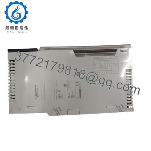
The input accommodates wide AC ranges (93–132 V or 170–276 V), which gives system designers flexibility when specifying for different power environments. Internal protections guard against overvoltage and overload on the DC side, preventing catastrophic damage to other modules. A local LED indicator (PWR OK, green) shows the supply status at a glance, and the module includes an alarm contact (NC 6 A, 220 V) for system-level fault signals.
Efficiency is not overlooked. Power dissipation is defined by a formula: 6 W + (1.5 × I_out), where I_out is in amperes. So at higher currents, losses scale predictably. Inrush currents can be significant, so upstream circuit breakers or supply sequencing may be needed for large installations.
From a reliability standpoint, the 140CPS11420 is rated for operation in 0–60 °C, and storage in –40 to +85 °C. Relative humidity is tolerated up to 95% (non-condensing). The module is also rated to operate at altitudes up to 5000 m (≈16,400 ft). It adheres to UL 508 and CSA C22.2 No. 142 for industrial equipment, and the module carries cUL certification. Immunity to electrostatic discharge (4 kV contact / 8 kV air) and electromagnetic fields (10 V/m, 80–2000 MHz) is built in.
One more powerful benefit: the module is well documented and supported, even though it is now discontinued. Schneider Electric published end-of-life timelines and suggested successor modules, and third-party firms support repairs and refurbishing. This support library ensures that even legacy installations can maintain uptime.
Technical Specifications Table
| Specification | Value / Range |
|---|---|
| Input Voltage (AC) | 115 V (93–132 V) AC / 230 V (170–276 V) AC |
| Input Current | 1,300 mA at 115 V / 750 mA at 230 V |
| Inrush Current | 38 A at 115 V / 19 A at 230 V |
| Rated Power | 130 VA |
| Fuse Rating | 2 A slow-blow |
| Output Voltage | 5.1 V DC |
| Output Current | 11 A standalone / 20 A summable (at 60 °C) |
| Power Dissipation | 6 W + (1.5 × I_out) |
| Alarm Contact | NC, 6 A at 220 V (power fault) |
| LED Status Indicator | 1 green LED (PWR OK) |
| Ambient Temp (Operating) | 0 to 60 °C |
| Ambient Temp (Storage) | –40 to +85 °C |
| Relative Humidity | Up to 95% (non-condensing) |
| Altitude | ≤ 5,000 m |
| Standards / Certifications | UL 508, CSA C22.2 No. 142, cUL, CE marking |
Installation & Maintenance Insights
When installing the 140CPS11420, orientation matters: ensure proper airflow across the module, and avoid mounting it near heat sources. Confirm the rack supports summable power modules and that the busbars or connectors are compatible. In systems using parallel (summable) mode, ensure equal impedance in wiring between modules to promote load sharing and avoid imbalance.
Use only recommended fuse types upstream—2 A slow-blow has been specified to tolerate transient surges yet protect against sustained overcurrent conditions. Be careful in sizing upstream circuit protection to account for inrush current, particularly if the system contains multiple power modules starting up simultaneously.
Label both AC input and DC output conductors clearly. Document the wiring and module serial numbers. In critical systems, I recommend deploying alarm contacts to a supervisory system (SCADA or BMS) so that a power supply fault triggers an audible or remote alert.
Periodically, check for dust accumulation, corrosion, or oxidation on connectors. Cleaning and re-torquing connection points (as per recommended torque spec) helps prevent loose contacts—often a sneak cause of failures in long-term installations. Ensure ventilation within the control panel stays within rated ambient temperatures, since excessive heat accelerates aging of power-supply capacitors.
Because the 140CPS11420 can run in summable mode, if you remove one module for repair, ensure the remaining modules can carry the entire load temporarily. Many integrators maintain a hot spare module to minimize downtime.
One practical tip: before commissioning a full rack, you can bench-test the power supply module by applying AC input and measuring the 5.1 V output under light load. This helps catch defects or internal issues before installation.
Finally, when doing firmware or control logic changes in a running system, always confirm the power modules are stable (LED on, no alarms), then sequence the logic modules. A power interruption during logic download sometimes introduces corruption, depending on the system architecture.


