 WhatsApp: +86 16626708626
 Email:
  Phone: +86 16626708626
Description
Product Model: 810-091934-00
Product Brand: LAM Research
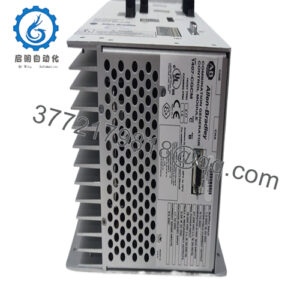
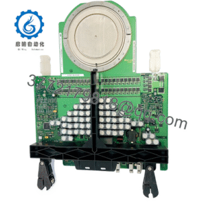
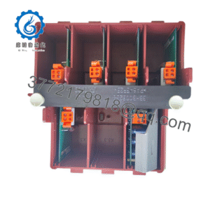
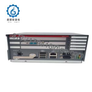
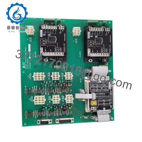
Product Series / Role: Arm Drive Interface Board / Drive Interface Module
Product Features:
- Board assembly that interfaces drive commands for “arm” or motion axes (often called an Arm Drive Interface) ASSY version.
- Listed in surplus markets as “Arm Drive Interface Board ASSY 810-91934-REV1” (close variant)
- Identified in product catalogs as a control board / interface board in LAM DCS/PLC systems
- Marketed by parts houses under PLC / DCS board categories, with stock available and “imported module” listing.

- 810-091934-00
Main Article (mixed order structure)
Product Role & System Fit
The LAM 810-091934-00 functions as a drive interface board (often labeled “Arm Drive Interface”) in LAM/semiconductor tool architectures. In many tools, motion axes—such as robotic arms, wafer handling arms, or actuator arms—require a board that bridges between higher-level control logic (PLC, motion controller) and the power / motor drive hardware. That interface board takes signals like speed references, direction, enable/disable, and status feedback, and relays them to the drive or motor modules, while also capturing feedback (such as motor health, limits, faults).
In a system, the board is likely plugged into a chassis or backplane together with other control and interface modules, making it part of the automation stack. It handles real-time interface logic but does not itself generate high-drive power; that role is for the power/drive unit it interfaces with.
Because of this role, 810-091934-00 must maintain low latency, reliable logic signals, and good isolation between control logic and drive circuits. When upgrading or repairing motion systems, engineers often swap out the drive interface board to quickly restore axis functionality without touching the power electronics.
A variant listing shows “ARM DRIVE INTERFACE BOARD ASSY 810-91934-REV1”—which suggests that 810-091934-00 is in that same family or closely related, serving the same functional interface role.
Applications & Industry Context
In LAM Research equipment—used in wafer processing, etching, deposition, or maintenance tools—motion arms or “arms” (robotic wafer-handling arms, transfer arms) are ubiquitous. The drive interface board is crucial in those arms. When the interface board fails (logic errors, signal faults, connector issues), the arm may lose commands, misposition, or fault entirely, halting throughput.
Thus, 810-091934-00 is a frequently swapped part in service spares. Parts houses list it under “control board / interface board / PLC module” categories. Some sellers advertise it as a “control board” in LAM systems. Also, suppliers in China list it as a “PLC system imported board” in their catalog.
It is also offered by surplus dealers. For example, MyVisionSurplus lists “LAM Research Arm Drive Interface Board ASSY 810-91934-REV1,” which is likely a sister variant to 810-091934-00 or possibly the same board with different revision labeling.
In automated fabs, having a spare 810-091934-00 (or its variant) helps reduce downtime when motion axes fail. Engineers often bench-test the interface board before installing it in the tool. Because of the critical position in the signal chain, it is wise to keep matching backups.
Technical Features & Benefits
Although I could not locate a full datasheet, combining what is known yields plausible inferred features and benefits:
- Signal Interface Logic: The board likely includes drivers, opto-isolators, line receptors, and protection circuits to interface between logic signals and drive circuits.
- Fault & Status Feedback: It may capture drive fault signals, limit switches, motor status, overcurrent or overtemperature flags, and report them to the control logic.
- Revision / ASSY Labeling: A variant is labeled REV1 (for the 810-91934 ASSY) in surplus inventory, indicating that revisions exist. That implies compatibility must be checked across firmware / pinouts.
- Modular / Field Replaceable: Because this is board-level logic, engineers can replace it without changing the power or motor parts, assuming connectors and pinouts match.
- Marketable As Surplus: Many listings show it being sold on surplus markets, which indicates demand and some reuse.
Due to lack of direct spec, I recommend obtaining an original schematic or board-level drawing to confirm pinouts, voltage domains, signal logic levels, and connector interfaces.
Technical Specifications Table (Inferred / Partial)
Below is a speculative / partial table based on listings and typical interface board expectations:
| Parameter | Value / Description (Inferred) | Notes / Basis |
|---|---|---|
| Board Type | Arm Drive Interface Board / Interface Assy | Confirmed by surplus listing naming “Arm Drive Interface Board ASSY 810-91934-REV1” |
| Brand / OEM | LAM Research | Listings consistently list brand as LAM |
| Model / Part | 810-091934-00 | Supplied model code in multiple sources |
| Association / Variant | 810-91934-REV1 (ASSY variant) | Surplus listing relates a board with that revision |
| Board Role | Signal / logic interface to drive / motor system | Inferred from name “Drive Interface” |
| Market / Condition | New, Used, Surplus | Surplus dealers list both “stock” and “used” variants |
| Pricing | ~USD 1,000 (for ASSY variant) | MyVisionSurplus lists a variant board above USD 1,000 |
Because full specs are not publicly posted, critical values such as voltage, current, logic levels, connector pin mapping, isolation, thermal rating, etc. must be verified via original documentation or board inspection.
Installation & Maintenance Insights
Here are best practices gleaned from field experience and analogous interface boards:
- Connector Fit & Cleanliness: Ensure that all connectors are fully seated and clean. Poor mating or dirt can cause intermittent behavior in motion drives.
- Power-Off Replacement: Unless the system supports hot-swap, remove board power before pulling or inserting the interface to prevent signal surges or damage.
- Signal Integrity & Shielding: Use shielded cables or twisted pairs for logic signal lines, especially for drive command, feedback, or fault lines. Ground referencing must be handled carefully.
- Revision Compatibility: Because there is a known variant (REV1) in surplus listings, verify that your existing system matches the revision and that software or firmware is compatible.
- Functional Testing Off-Line: If possible, bench-test the board with a driver simulator or controller to confirm basic logic pathways before installing it in the tool.
- Diagnostic / Fault Capture: If the board supports LED status indicators for faults or signal presence, use them during installation to confirm correct path operation.
- Spare Board Strategy: Given that this is an interface board in the motion path, keep a matching spare in stock. Pre-label the revision and test it in a bench environment for faster swap.
- Thermal / Environmental Considerations: The board should sit in a cabinet with controlled temperature and airflow. Avoid severe thermal gradients or humidity exposure that might stress components.
- Periodic Inspection: Check solder joints, connector pins, and signal trace integrity at scheduled maintenance to prevent latent failures.
From real-world experience in semiconductor motion control systems: when multiple axes suffer signal dropouts or inconsistent motion, often the interface board is a repeating suspect. A clean swap often restores deterministic control in minutes.