 WhatsApp: +86 16626708626
 Email:
  Phone: +86 16626708626
Description
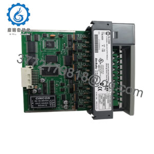
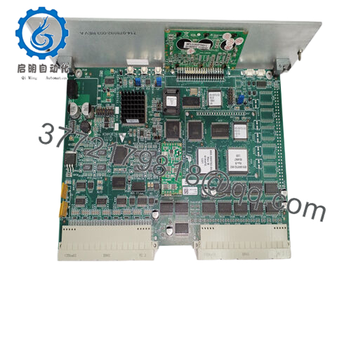
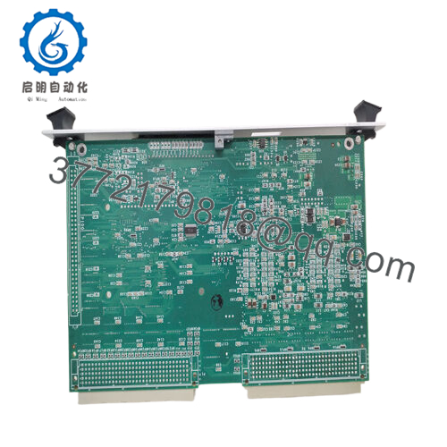
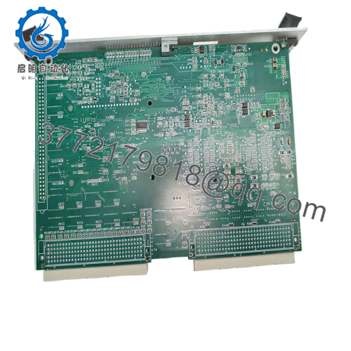
Product Model: 810-069751-114
Product Brand: LAM Research
Product Series / Role: Node Board / Junction / Edge Detector / Type 41 Board
Product Features:
- Node Board, Type 41 (communication / junction board) for LAM systems (often called “node board” listings)
- Functions as edge detector / junction board in tool subsystems (gas box, signal distribution)
- Supplied as PCB / PCBA (printed circuit board assembly) with new / used condition options, 365-day warranty in some supplier catalogs
- Utilized as a communication board in LAM’s module stack (handles fiber / inter-module links)

- 810-069751-114
Product Role & System Fit
In LAM tool electronics, 810-069751-114 is best understood as a node / junction / edge detector board (often called Type 41 Node Board). In several listings, it appears under “NODE BOARD, TYPE 41” designation.
Its role is to act as a local distribution and signal interconnect hub—receiving signals from upstream modules (control logic, fiber links, sensor domains) and relaying them, perhaps after edge detection, to downstream modules. In many modular tool architectures (gas boxes, valve modules, sensor networks), such boards sit between main chassis and remote modules to manage communication, signal conditioning, wiring consolidation, and possibly protocol translation.
Some suppliers explicitly call it a communication board, indicating that it participates in inter-module signaling (fiber or wired). One listing describes it:
“During installation … 810-069751-114 located near the Main Chassis and additional RXM and Expansion Chassis connected to this … must ensure that all fiber-optic ST® connectors are fully seated and engaged.”
Thus, the board not only handles local I/O or edge processing, but also forms part of a fiber or network backbone in the tool control electronics. It may bridge between main chassis signals and remote extension chassis (RXM).
In summary, 810-069751-114 is a communication / node board that fits into a modular architecture, acting as a junction and interface hub that ensures robust signal flow in LAM tools.
Applications & Industry Context
In semiconductor manufacturing, tool downtime is extremely costly. Many failures stem from miscommunication, signal breakdowns, or module disconnects rather than outright mechanical faults. Node / junction boards like 810-069751-114 are critical because they form the nervous system of module-to-module communication.
You’ll find this board in the electronics stack of LAM tools—particularly in gas box domains, remote module extension racks, or sensor / IO domains. It might be located adjacent to main chassis, between fiber or ribbon cables, or in expansion chassis where remote modules attach.
When a fiber link fails or modules downstream lose connectivity, technicians often check the node board as an early suspect. Because it is modular and field-replaceable, it is commonly stocked in parts inventories.
One listing calls it “Lam Research PCB edge detector junction board,” which suggests it also performs signal edge detection (identifying transitions) before passing signals along. In that context, “edge detector” means it may convert or clean up pulses (rising/falling edges) before distributing them. In effect, it adds gating, buffering, or filtering on signals to maintain integrity over longer runs.
Suppliers often list 365-day warranty for new or used stock of 810-069751-114 in their catalog. This underlines its recognized role as a spare part in reliability-critical systems.
Technical Features & Benefits
Here’s what we can infer (or compile) about the 810-069751-114 board, along with its advantages and caveats:
Communication / Junction Capabilities
The board likely supports a mix of communication links: fiber-optic connectors (e.g. ST connectors), wired digital logic, and perhaps differential signaling for module interconnect. The listing for fiber-optic ST® connector seating emphasizes that fiber links are part of its function.
Edge Detection / Signal Conditioning
As part of its “junction / edge detector” characterization, the board may perform pulse shaping, signal thresholding, or clean up of logic edges before dispatching downstream. That helps maintain robust signal quality over cable runs or noisy environments.
Module Density & Connectivity
Given its role as a node hub, the board likely offers numerous connectors, internal trace routing, and interconnect paths. It likely consolidates multiple input sources into fewer downstream buses.
Robustness & Form Factor
As a backplane / midcard in a control electronics domain, it probably is designed for stable operation under temperature cycles, vibration, and ESD. Many of these boards are multi-layer PCBs with controlled impedance. Supplier listings describe it as PCBA NODE TYPE 41 CE, with warranty and quality assurances.
Market Availability & Warranty
Supplier catalogs affirm that 810-069751-114 is available as original module (new / used) with 365-day warranty. This helps buyers trust refurbished or used stock.
From a benefits perspective, having a robust node board improves modular resilience: if one downstream module loses connectivity, the node acts as a localized hub that can be replaced without rewriting upstream logic. Signal integrity, edge detection, and buffering functions protect downstream components from electrical noise or signal degradation.
One practical advantage: in systems where extension racks are used, replacing the node board often reinstates connectivity to multiple modules at once, saving significant troubleshooting time.
Technical Specifications Table (Inferred / Partial)
Because no full datasheet is publicly available, the following table is based on listings and logical inference. Use it as a starting outline and refine when OEM data is available:
| Parameter | Value / Description (Inferred) | Notes / Source |
|---|---|---|
| Board Type / Role | Node Board / Junction / Edge Detector | Listing: “NODE BOARD, TYPE 41” |
| OEM / Brand | LAM Research | All listings attribute it to LAM |
| Model / Part Number | 810-069751-114 | That is the consistent PN in listings |
| Communication Role | Communication / signal routing / fiber interconnect | Listings call it “communication board” |
| Edge Detection Function | Likely includes edge detection / signal conditioning | Supplier listing says “edge detector junction board” |
| Availability | New / Used / OEM stock | Supplier listing: “New / Used / Original module” |
| Warranty | 365 days (supplier) | Supplier listing gives 365-day warranty |
| Connector Type | Fiber ST connectors (at least) | The installation note mentions fiber-optic ST connectors for this board |
| Weight / Size (approx) | Unknown / not disclosed | No credible listing shows dimensions or weight |
| Use Price | ~$1,600 (as-is listing) | eBay listing shows used price ~US$1,662 |
Absent official data, values for voltage domains, power consumption, signal levels, trace impedance, bandwidth, isolation, and timing must be sourced from internal tool documentation.
Installation & Maintenance Insights
When working with 810-069751-114, here are best practices and caveats:
- Fiber Connector Integrity
Because fiber ST connectors are part of its communication chain, ensure they are fully seated, locked, and clean. The listings explicitly warn that mismatched or loose ST connectors may degrade communication or lead to faults. - Aligned Insertion / Backplane Fit
Insert the board carefully into its slot or chassis to avoid bending connectors or damaging traces. - Power and Signal Off During Swap
Unless the system supports hot-swap of node boards, de-energize upstream signals before removal or insertion to prevent surges or signal corruption. - Testing Off-Tool
If possible, test the board in a bench environment with dummy modules or link simulators. Check communication channels, signal continuity, LED status, and edge behavior before deploying. - Maintain a Spare Board
Because it’s a critical communication hub, maintain a known-good 810-069751-114 board in your inventory for rapid swap. - Inspect Connectors & fibers
Over time connectors can wear, fibers can degrade, and optical alignment can drift—regular inspection and cleaning is vital. - Firmware / Configuration Matching
If the board holds configuration, version or calibration data (e.g. node addressing or routing tables), ensure the replacement is compatible or preconfigured. - Shielding & Grounding
Ensure that the board’s signal and fiber anchoring is done in a way that avoids ground loops or EMI coupling. Use grounding references appropriate to the system architecture. - Environment Control
Keep the board within ambient temperature/humidity tolerances. Avoid exposure to condensation, particulate ingress, or mechanical shock.
In field experience, when multiple downstream modules lost link simultaneously, technicians often trace back to the node board for failure. A clean replacement of 810-069751-114 often restores communication across many modules at once.