
 WhatsApp: +86 16626708626
 Email:
  Phone: +86 16626708626
Description
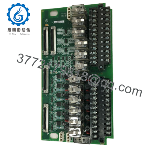
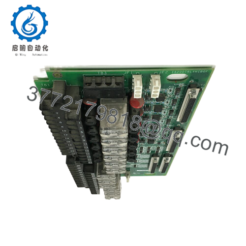
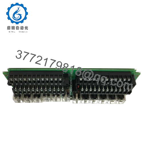
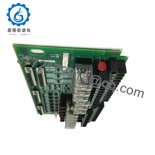
Product Model: IS200TRLYH1BGF
Product Brand: GE (General Electric)
Product Series: Mark VIe / TRLY family
Product Features (key strengths):
- Implements relay / trip output functionality, typically used for turbine emergency trip or protection circuits
- Designed to integrate into GE’s Mark VIe / Speedtronic control architecture, with standardized connectors and form factor
- Built for industrial harshness—vibration, temperature swings, electromagnetic interference
- Provides diagnostic and fault feedback on relay output status to the controller

- IS200TRLYH1BGF

- IS200TRLYH1BGF

Product Role & System Fit
The IS200TRLYH1BGF is a relay / trip output terminal board in the GE Mark VIe (and compatible Speedtronic) control ecosystem. Its job is to convert internal control logic decisions into physical relay outputs—often for emergency trip, overspeed shutdown, or other safety-critical actions.
In a turbine control cabinet or PDM (Power Distribution / I/O module) environment, the TRLY board sits between the control logic modules and the external solenoids, valves, or actuators that must be driven during a protection event. The logic sends a command; the TRLY board energizes the proper relay(s) to actuate a shutdown or safety device.
Because of its role in safety and reliability, IS200TRLYH1BGF is designed to be robust, predictable, and feedback-capable (i.e. it should be able to report relay stuck, coil burn, or contact feedback status). It must integrate seamlessly with the Mark VIe backplane, communications buses, and diagnostic system, so that the main controller can oversee not only logic but also the health of its output stage.
Unlike generic relays, this module is part of a controlled, redundant, and monitored system. In redundant architectures, you might have multiple TRLY modules or parallel protection paths; in simpler systems, the TRLY board is the designated output interface for all trip logic.
In many designs, the “TRLY” name stems from “Trip Relay.” The “H1BGF” suffix implies a revision or variant (H1B family, with “GF” perhaps denoting factory variant or internal revision). Because GE tends to reuse naming conventions across Mark / Speedtronic product lines, this module is likely closely related to other TRLY boards, but with its own output ratings, relay count, contact style, or diagnostic enhancements.
This board is neither the controller (CPU) nor a general I/O board—it is specialized for relay / trip outputs. It must be placed in the proper relay / output slot, and wired to field devices (solenoids, valves, shutdown circuits). The harness must match the expected pinouts and rating of this board.
Applications & Industry Context
In power plants, gas turbines, combined-cycle installations, and industrial plants, the ability to trip equipment safely—and reliably—is nonnegotiable. The IS200TRLYH1BGF is commonly used in those environments to provide the final “actuation” stage for critical shutdowns, interlocks, and safety logic.
For instance, in a turbine, overspeed or over-temperature logic in the CPU issues a shutdown command; the IS200TRLYH1BGF carries that command forward to the trip solenoids, emergency stop valves, or protection circuits. A fault there means the plant cannot safely shut down, so the module must be robust, monitored, and redundant where required.
In retrofit scenarios, when upgrading older Mark or Speedtronic systems to Mark VIe, the TRLY boards are often replaced or paralleled. Upgrading to IS200TRLYH1BGF (if compatible) helps maintain consistency in connector layouts and supports newer diagnostic capabilities.
In petrochemical, refining, or process plants, TRLY boards are also used not just for turbine protection, but for critical safety shutdown circuits, emergency logic, and interlocking sequences. Wherever a logic decision must become a physical, fast, and reliable action, a TRLY board like IS200TRLYH1BGF is the interface point.
In systems where redundancy is deployed, the TRLY board often works in conjunction with other protection modules like TREG (Trip positive supply), TRPG (trip negative supply), VPRO (protection logic), or TPRO (protection decision modules). The TRLY output module is what gives physical effect to the protection logic.
Because industrial environments are noisy, have vibration, and may be subject to power surges or transients, the TRLY boards must be built to tolerate that while preserving contact integrity. Also, early diagnostic detection of a failing relay coil or contact is valuable to maintenance teams before an actual trip event fails.
Technical Features & Benefits
Let’s explore features we’d expect in a module like IS200TRLYH1BGF and what benefits they offer.
Relay output capability with appropriate voltage / current ratings
The board is expected to drive field devices (solenoids, actuators, shutdown valves). It must supply the needed coil voltage (for example, 24 V DC, 125 VDC, or other standard turbine voltage) and sufficient current capacity. The relay contacts must handle the load and provide reliable switching under load.
Isolation and protection between logic and field circuits
Because field circuits may carry noise, surges, or even shorts, the TRLY board must isolate the logic side. Protective components—diodes, surge suppressors, fuses, contact suppression networks—are often built in to protect both sides.
Diagnostic feedback / status monitoring
A highly desirable feature is feedback contacts or sensing circuits so the controller can verify whether a relay actually energized, or detect a stuck contact/faulted coil. This allows preventive maintenance or fault detection before a critical event.
Redundancy / failover capability
In critical plants, you may have dual or redundant TRLY paths. The module should support configurations that allow one relay board to take over if another fails, or allow the controller to select the healthiest path.
Rugged design for industrial conditions
As with other GE Mark / Speedtronic modules, the TRLY board must endure vibration, temperature extremes, electromagnetic interference, and long life under continuous operations.
Standard connector and integration compatibility
Mechanically and electrically compatible with the GE Mark VIe / Speedtronic terminal layout, backplane connectors, and harness wiring standards. That helps installers drop the board in without massive rework.
Fast response times
In trip or protection applications, relay switching must be prompt (milliseconds or less). The board must have minimal delay and deterministic switching behavior.
Modular serviceability
If a relay coil or contact degrades, the board should allow for replacement or maintenance of relay elements without full system replacement, ideally with modular relays or field-replaceable components.
Given the lack of public datasheets for IS200TRLYH1BGF, these features are typical expectations in TRLY boards of GE / Mark / Speedtronic families; you should verify exact coil voltages, contact current, number of relays, and diagnostic paths from your OEM or system documentation.
Technical Specifications Table
Below is an inferred / template table based on typical TRLY module behavior. Replace or confirm with actual documentation.
| Specification | Expected Value / Range (Example) |
|---|---|
| Model | IS200TRLYH1BGF |
| Function | Relay / trip output terminal board |
| Compatibility | GE Mark VIe / Speedtronic control systems |
| Output Channels | (e.g. 3 or more relay outputs—depending on board version) |
| Relay Contact Type | Normally open / normally closed, depending on design |
| Coil Voltage | (e.g. 24 V DC, 125 V DC or as per system) |
| Contact Current Rating | e.g. 2 A, 5 A, 10 A (verify) |
| Control Logic Interface | Backplane signals / control logic bus |
| Isolation / Protection | Diodes, surge suppression, fuses, isolation barrier |
| Diagnostic Feedback | Relay state sensing, fault detection output |
| Operating Temperature | e.g. –40 °C to +70 °C |
| Mounting / Form Factor | Fit in TRLY output slot or relay board bay in control cabinet |
| Environmental Tolerance | Designed for vibration, EMI, industrial conditions |
| Response Time | e.g. < 10 ms or less from command to actuation |
| Redundancy Support | Capability for redundant relay paths or failover |
Again, these figures are illustrative. Confirm with your system manual or the GE parts datasheet for exact values.
Installation & Maintenance Insights
Here are practical tips for installing and maintaining IS200TRLYH1BGF to ensure reliability and safety.
Pre-install inspection
Before insertion, inspect the board for bent pins, solder joint cracks, dust, or corrosion. Check relays (if visible) for physical damage or discoloration.
Power down / de-energize
Always de-energize control power / field power before installing or removing the module to prevent arcing or damaging relays or connectors.
Precise alignment with connectors
Align the backplane / harness connectors carefully. A misalignment can bend pins or lead to intermittent contacts. Gently seat the board rather than forcing it.
Cable harness and wiring
Use proper gauge, shielded conductors for the relay coil wiring. Provide strain relief and ensure field wiring paths do not induce mechanical stress on the board.
Grounding & shielding
Ensure solid ground reference, shielded wiring for relay control circuits, and avoid routing power wiring across relay signal paths. Good grounding greatly reduces spurious switching or noise-induced faults.
Ventilation and clearance
Although relays may not generate huge heat, the board may be near power circuits. Leave clearance and airflow to avoid heat build-up.
Initial functional test
After installation, perform known-command tests: energize each relay from the control logic, confirm the output device activates, and verify diagnostic signals reflect the actual state.
Diagnostic monitoring
Regularly monitor controller logs for relay fault events, stuck-coil errors, or contact feedback mismatches. Address anomalies before a field event.
Periodic inspection / cleaning
Visually inspect the board (annually or semiannual): look for discoloration, moisture ingress, dust, or mechanical loosening. Use dry air or approved nonconductive cleaning tools.
Relay lifecycle management
Relays have mechanical wear. If the board uses modular relays, consider periodic replacement or testing. Track operation cycles if possible.
Spare module readiness
Keep a spare IS200TRLYH1BGF (same revision) in inventory. Label revision, date, and test status. In the event of failure, swapping is much faster than troubleshooting under process pressure.
After swap validation
Any time you replace the board, retest all outputs under controlled conditions to ensure correct functioning and that no wiring is inadvertently misconnected.
Version compatibility check
If your system has multiple TRLY board revisions, confirm your replacement matches or is backward-compatible (H1B, etc.). Mismatched revisions may cause pin mapping or diagnostic incompatibility.
In a real-life example, a plant had a relay fail on a TRLY board. Because diagnostic alarms flagged a “failed contact” state ahead of time, maintenance swapped out the module during a scheduled shutdown rather than in an emergency, avoiding costly unplanned downtime.
Related Models & Variants
Here are some related relay / trip / output boards in GE / Mark / Speedtronic lineups you might see:
- IS200TRLYH1B – A variant in the H1B family (similar outputs, possible revision)
- IS200TRLYH1A – Earlier revision in the TRLY family
- IS200TRLYH2B – Higher-capacity or dual relay version
- IS200TREH1A / TREG / TRPG boards – Complementary boards supplying trip power or negative side of trip circuits
- IS200TSVOH1B – Signal / status board often used alongside TRLY boards
- IS200VPROH1B – Protection / logic boards that interact with relay output modules
- IS200TRLYH1BG – Another variant (without “F”) that may differ slightly in revision
When substituting or upgrading, always check mechanical and electrical compatibility (pinouts, contact ratings, wiring harness) before installing. The suffix differences (H1B / H1BGF / H1BG) often represent firmware or connector tweaks.


