


 WhatsApp: +86 16626708626
 Email:
  Phone: +86 16626708626
Description
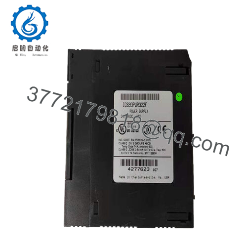
Product Model: IC693PWR322F
Product Brand: GE (GE Fanuc)
Product Series: Series 90-30 (PLC family)
Product Features (key strengths):
- Provides three isolated outputs: +5 VDC, +24 VDC Relay, +24 VDC Isolated, enabling both backplane and field I/O power
- Operates from nominal 24 V or 48 V DC input over a wide range (21–56 V)
- 30 W total load capacity, supporting moderate PLC and peripheral loads
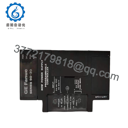
- Equipped with RS-485 communication port for monitoring, plus LED indicators (PWR, OK, RUN, BATT) for status diagnostics
Applications & Industry Context
In many industrial automation systems, the power supply is often overlooked until it fails — yet it is literally the lifeline of PLC racks and peripheral modules. The IC693PWR322F is designed precisely for GE Fanuc’s Series 90-30 PLC systems, where reliability, isolation, and diagnostic capability are essential. Whether deployed in manufacturing, process control, water utilities, or OEM equipment, this power module transforms raw DC input into the regulated voltages needed by the control backplane, I/O modules, relays, and sensors.
Take a chemical processing plant using a 90-30 control rack: the I/O modules, analog/digital cards, and relay modules all require stable +5 V and +24 V rails. The IC693PWR322F ensures those rails are delivered faithfully, even under transient load swings or fluctuations in the plant DC bus. In water treatment or wastewater systems—where field wiring distances are long, and noise or voltage drop is a concern—its isolation and robustness help prevent faults from propagating.
In retrofits of aging systems, one common failure point is power supply modules. Replacing with IC693PWR322F often stabilizes an otherwise unpredictable rack, reducing brown-out resets or flickering I/O statuses. In OEM machinery, where space and cost constraints matter, the 30 W capacity balances modest load support without oversizing, while the diagnostic RS-485 port gives system integrators feedback on health. Because the module is part of the Series 90-30 ecosystem, it fits existing chassis, backplanes, and wiring layouts—making it a drop-in upgrade for many legacy PLC deployments.

- IC693PWR322F
- IC693PWR322F
Product Role & System Fit
Within a GE Fanuc Series 90-30 rack, IC693PWR322F acts as the principal DC power supply module. It sits typically in the leftmost slot of the 90-30 baseplate, delivering regulated voltages to the backplane and optionally to external field modules. The module splits its outputs: one branch for +5 V (primarily for internal logic/backplane cards), one for +24 V Relay, and another for +24 V Isolated (for input modules or external loads).
It is not a CPU, I/O, or communication card — it is fundamental infrastructure. Without it, the entire 90-30 system has no stable internal power and cannot operate. Its compatibility with the 90-30 architecture is important: connectors, mechanical footprint, and pin mapping match other modules in the family. In many installations, the control cabinet’s DC bus (24 V or 48 V) is wired to feed this module, which then converts and distributes internally.
Because it supports both 24 V and 48 V DC input ranges, IC693PWR322F is flexible for plants using either DC standard. It can also assist in redundancy schemes; though not redundant by itself, you might pair with redundant modules or backup DC sources in higher-availability systems.
When configuring, engineers must size the downstream load so that the cumulative draw on the +5 V and +24 V outputs does not exceed the 30 W rating. In practical systems, one often leaves a 20–30% margin for load growth or startup surges. The module’s RS-485 port and LED indicators give insight to health and faults, helping integrators detect anomalies early.
Technical Specifications Table
Below is a summary spec table for IC693PWR322F (based on supplier datasheets and field references):
| Specification | Value / Range |
|---|---|
| Model | IC693PWR322F |
| Series / Platform | GE Fanuc Series 90-30 |
| Input Voltage (Start) | 21 to 56 V DC |
| Input Voltage (Run) | 18 to 56 V DC (can operate down to ~18 V under some loads) |
| Nominal Input Voltage | 24 V or 48 V DC |
| Output Power | 30 Watts total |
| +5 V Output | Up to ~15 W (for backplane / logic) |
| +24 V Relay Output | Up to ~15 W |
| +24 V Isolated Output | Up to ~20 W |
| Holdup Time | ~14 ms minimum under rated loads |
| Inrush Current | Up to ~4 A peak for 100 ms |
| LED Indicators | PWR, OK, RUN, BATT (status indicators) |
| Communication Port | RS-485 (9-pin D-sub) for monitoring and programming |
| Mounting Position | Leftmost slot in 90-30 baseplate rack |
| Operating Environment | Industrial temperature / conditions (consult full datasheet) |
| Lifecycle | Discontinued / legacy part in many catalogs |
As always, consult the exact revision datasheet (F-revision) in your system to confirm pinouts and tolerances.
Technical Features & Benefits
Let me walk you through what gives IC693PWR322F its staying power in industrial systems:
Multiple isolated outputs for versatility
One of its strengths is that it offers three distinct outputs: +5 V for internal logic/backplane, +24 V Relay for relay modules, and +24 V Isolated for input modules or external I/O circuits. These isolated outputs help segregate noise, reduce cross-interference, and ensure faulty loads don’t drag down the logic side.
Wide DC input tolerance
The ability to accept anywhere from ~21 V to 56 V DC gives engineers flexibility when designing the DC bus. Whether the plant uses 24 V DC, 48 V DC, or mixed DC sources, IC693PWR322F adapts. Under ideal input, it starts at ≥21 V DC and can run even down to ~18 V in some conditions.
Decent holdup and inrush handling
With ~14 ms holdup and 4 A inrush capacity, the module can absorb short disturbances, helping prevent resets or brownouts under load surges.
Status diagnostics and communication
LED indicators (PWR, OK, RUN, BATT) provide rapid local insight into module health. The RS-485 port also allows remote monitoring, which is valuable for system diagnostics and integrating supply health into your automation or SCADA layers.
Legacy compatibility and drop-in fit
Because it’s part of the 90-30 family, replacing older or failing power modules with IC693PWR322F is often straightforward. You maintain rack layout, wiring, and mechanical footprint, reducing retrofit risk.
Reasonable power capacity for many systems
With 30 W total, it supports moderate I/O counts and relays. While not high capacity, in many legacy PLC racks, that is sufficient. Its rating encourages system designers to manage loads prudently and avoid overextending.
That said, due to its legacy status, many modern systems push beyond what it can deliver — so in retrofits or expansions, users frequently monitor load margins, plan for future derating, and sometimes pair with secondary supplies.
Installation & Maintenance Insights
Proper installation and periodic care can significantly extend the life and reliability of IC693PWR322F in your system. Here are field-tested tips:
Slot and orientation
Install the module in the leftmost position on the baseplate, per Series 90-30 convention. Ensure backplane connectors align cleanly before pressing the unit in.
Power sequence and isolation
Always disconnect DC bus input before inserting or removing module. Avoid hot-swapping unless your design explicitly supports it. Consider soft ramping the input voltage to minimize surges.
Wiring and connectors
Use adequately gauged, low-resistance copper wiring for DC input. Secure mechanical connections firmly; loose wiring is a frequent cause of intermittent issues. Provide strain relief and route cabling to avoid vibration fatigue.
Cooling and ventilation
While the module doesn’t produce extreme heat, neighboring modules and dense racks can create heat pockets. Provide airflow or ventilation slots near the power supply. Avoid stacking covers or barriers that block airflow.
Diagnostics and LED review
During commissioning, verify PWR, OK, RUN, and BATT indicators. The RS-485 port should respond to monitoring commands. Periodically check status logs or remote diagnostics for anomalies like battery low or voltage drop warnings.
Battery / backup memory
Although IC693PWR322F includes battery backup for RAM retention, battery performance degrades over time. Replace backup battery in line with preventive maintenance schedules. Use correct battery type (e.g. IC693ACC301) per original specification.
Inspect and clean
Quarterly, visually inspect module for dust, discoloration, or stress. Use clean compressed air (dry) — no liquids. Check for connector corrosion or loosening due to vibration.
Spare module strategy
Keep a matched spare IC693PWR322F (same revision, firmware) in inventory. In emergencies, swapping is faster than diagnosing under duress. Label spares with serial, revision, installation date.
In one real-world case, a plant had intermittent resets in a 90-30 rack. After tracing, they found the power module’s input wiring had loosened slightly. Because the LED indicators dimmed just before failure, operators were able to schedule the repair before complete shutdown — a reminder that the diagnostic features matter.
Related Models / Variants
Here are several related GE / Fanuc / Series 90-30 power supply modules or variants to compare:
- IC693PWR322 – Baseline model series (non-revision specific) with similar 30 W capacity and outputs IC693PWR322A / B / C / D / E – Earlier revision versions of the same module; F is a later revision
- IC693PWR330 – A higher-capacity AC/DC power supply version, sometimes used for larger load systems
- IC693PWR321 – A simpler or lower-power supply variant in the 90-30 lineup
- IC693PWR331 – Variant with enhanced power or alternate inputs in some legacy systems
- IC693PWR330F – Revision-F version of the AC/DC supply line, in scenarios requiring AC input
- IC693PWR332 – Alternative power module with different ratings or redundancy support
These models differ primarily in capacity, input type (AC/DC), output isolation, and revision compatibility. Always confirm mechanical fit and interface compatibility before substituting.


