 WhatsApp: +86 16626708626
 Email:
  Phone: +86 16626708626
Description
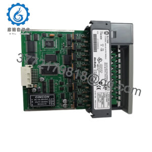
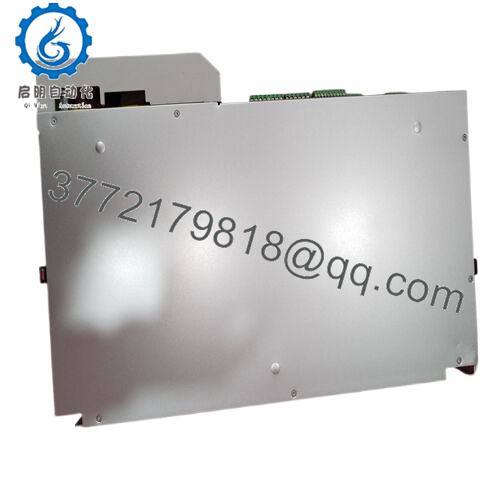
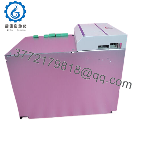
Product Model: HVE04.2-W075N
Product Brand: Bosch Rexroth (Indramat)
Product Series: HVE (HVE / HVR 2nd Generation)
Product Features:
- 75 kW nominal AC → DC bus supply, continuous DC bus power ~90 kW
- Regenerative / bleeder capacity (peak 270 kW, continuous bleeder ~2.5 kW)
- Compatible with 3× 380–480 VAC input (±10 %) at 50/60 Hz
- Built-in blower cooling, diagnostic HI display, modular rack integration
Product Role & System Fit
The HVE04.2-W075N is a servo drive power supply (DC bus supply) module in Rexroth’s HVE / HVR 2nd Generation family. It isn’t a servo drive itself; instead, it sits upstream and conditions AC mains into a DC bus voltage that feeds downstream drives (the DIAX04 family, or similar Rexroth/Indramat servo controllers). The HVE variant produces an unregulated DC bus (i.e., the bus voltage floats depending on input), while HVR units are the regulated counterpart.
In a typical setup, one HVE04.2 module powers multiple servo axes via a shared DC bus. The drives tapping into that bus draw current and handle motor control; the HVE handles bulk power conversion, energy regeneration, and bus management. Because of its modular design, it fits into rack or control cabinet configurations in industrial motion systems.
One nuance: because it supplies an unregulated DC bus, your system design must allow for bus voltage variation (within acceptable tolerances for downstream drives). This adds some flexibility—but also requires proper planning of voltage margins in your entire drive train.
It’s often paired with GLD chokes or DC bus smoothing modules (e.g. GLD20) to optimize performance, especially under high dynamic or regenerative loads.
Because HVE04.2-W075N supports substantial power (75 kW nominal and ~90 kW continuous bus) it often underpins medium-to-large multi-axis systems—packaging lines, machining centers, automated test rigs, robotics, or motion cells where multiple servo drives share a common power bus.

- HVE04.2-W075N
Technical Features & Benefits
Let’s examine what gives HVE04.2-W075N its strength and what trade-offs to watch.
Power & Regeneration Capability
Nominally rated for 75 kW AC → DC conversion, it actually supports a continuous DC bus power of ~90 kW according to vendor data. For short durations, it can handle much higher loads: peak DC bus power of 270 kW (0.3 s) and short-term (~30 s) higher outputs when paired with proper chokes.
When servo axes decelerate, kinetic energy is fed back into the bus (regeneration). The HVE04.2 includes bleeder / regeneration capability—its bleeder circuits absorb or dissipate excess energy. The continuous bleeder power is ~2.5 kW; peak bleeder power is 270 kW.
Because of that regeneration support, your system has opportunities for energy efficiency, especially in cyclical motion where braking energy is significant.
Input / Voltage & Electrical Conditions
The unit accepts 3-phase AC input from 380 to 480 V (±10 %) at 50–60 Hz. Internally, it rectifies to the DC bus, but with the unregulated design, bus voltage tracks input characteristics.
The maximum AC input fuse spec is 160 A for the power supply side. In some configurations, the control voltage supply is tied to the same mains, but in certain systems, you may decouple the control bus to preserve diagnostics after power shutdown.
HVE04.2 units may be combined in parallel (master-slave) to increase total DC bus power. But parallel operation demands identical unit types (same version) and synchronized configuration.The emergency-stop circuits, balancing chokes, and bus wiring become more complex in multi-unit setups.
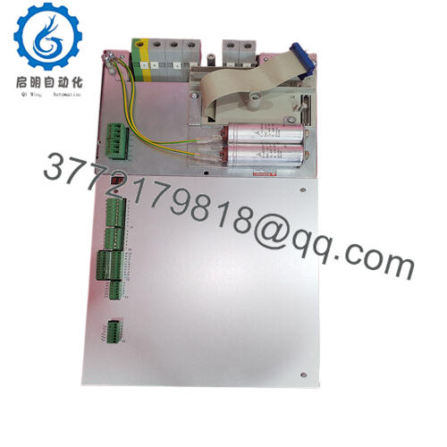
Diagnostics & Monitoring
A front-mounted “HI diagnostic display” communicates status, fault codes, and energy flow. This usability feature speeds commissioning and troubleshooting—seeing error codes in situ is a big plus when a module is buried deep in a rack.
Because it’s modular, field replacement of sections, modules, or power components is easier—rather than discarding the unit entirely.
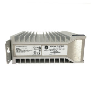
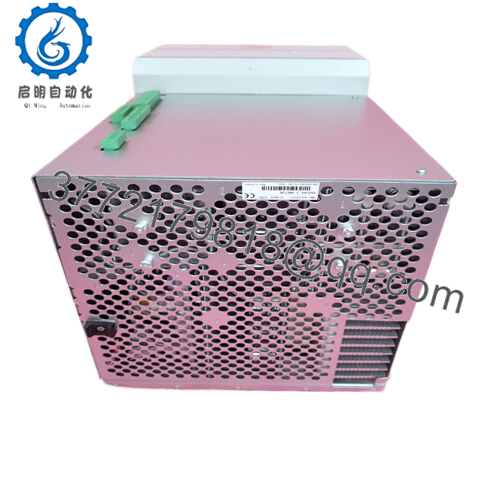
Cooling & Thermal Design
The supply has a built-in blower (internal forced-air) to manage losses. Ambient operating temperature spec is nominally +4 °C to +45 °C (for full rated performance) (some derating allowed up to ~55 °C)
One limitation: the protection rating is IP10—i.e. no dust or splash protection. This means the module should be installed inside a dust-controlled, clean cabinet.
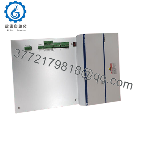
Modularity & Integration
Its rackable form factor and modular design mean it integrates well into standard drive stacks of Rexroth systems (e.g. DIAX04). Integration with GLD DC bus chokes, balancing chokes, and bus capacitance modules allows designers to tune the bus response, smoothing, and regenerative behavior.
Because it’s part of Rexroth’s motion ecosystem, documentation, repair paths, and compatibility with legacy systems remain available.
All these features combine to make HVE04.2-W075N a robust backbone power supply in multi-axis motion systems—if you carefully design your bus, cooling, wiring, and regeneration paths.
Applications & Industry Context
Where do you find HVE04.2-W075N in the field? Here are realistic use cases and constraints.
In machining centers or metal fabrication cells, it often powers multiple servo spindle or feed axes in a rack. Because spindle motion often has large kinetic energy changes, the regenerative capacity is useful for returning braking energy.
In packaging lines with many servo axes (conveyors, pick heads, indexing), consolidating power via a supply like HVE04.2-W075N reduces duplication and simplifies cabinet design.
In automated test or motion simulation rigs, the demand for dynamic, high-peak loads (for acceleration / deceleration) fits well with the high peak power capabilities. The unregulated bus approach gives flexibility to match bus voltage to load demand.
In retrofit or legacy Rexroth installations, it’s a common drop-in replacement for older HVE modules (HVE04 series). Because Rexroth’s modular design hasn’t radically changed for HVE / HVR 2nd gen, these units are used to preserve existing drive investments.
One practical note: Because HVE04.2-W075N has limited protection (IP10) and is sensitive to ambient dust or ambient heat, in more challenging environments (food, dust, spray, high humidity) you’ll often see it enclosed in a ventilated but filtered cabinet. Periodic cleanouts, vent maintenance, and cabinet airflow design become as important as electrical wiring.
I’ve seen systems where multiple HVE04.2 modules were paralleled to handle very high-load systems—e.g. in a 12-axis milling cell. But those setups required special attention to balancing, emergency-stop wiring, and fault synchronization. That leads us into installation and maintenance recommendations next.
Installation & Maintenance Insights
Installing HVE04.2-W075N properly is critical to ensure reliable lifetime performance. Below are field-proven tips and cautions.
Mounting, Venting & Cabinetry
Mount the unit vertically per manufacturer orientation; avoid tilting or restricting airflow. Leave clearance around inlet and outlet vents so blower cooling isn’t impeded. Use filtered ventilated panels if your cabinet is dusty. Because the unit runs warm (power losses scale), ensure ambient air can enter and exit freely.
Place the module away from external heat sources (transformers, drives, power resistors) to prevent thermal coupling. In tight cabinets, isolation barriers or forced-exhaust fans can help.
Wiring & Cable Routing
Use heavy-gauge, low-impedance copper for the AC input and DC bus leads. Keep wiring length short to minimize voltage drop or inductance. In systems with multiple modules, ensure proper bus balancing wiring, especially if paralleling two HVE units.
Emergency-stop circuits (soft start circuits) are critical. The maximum total resistance allowed in the E-stop wiring for HVE04.2 is ~350 Ω; beyond that, the internal contactor may not reliably pick up (leading to “soft-start error”). Also, the cross-section of those wires is limited to around 1.5 mm² / AWG16, and distance between HVE units should be kept modest unless routed carefully.
If paralleling two modules, you need matching balancing chokes (e.g. KD or GLD types) and often coordination of emergency-stop circuits to ensure one module doesn’t overload the other.
Ensure control voltage wiring (if separated) is properly protected and fused. In some installations, designers decouple control voltage supply to preserve diagnostics even after power is removed.
Commissioning & Testing
When first powering, watch the soft-start sequence carefully. Faults like “16 – soft start error” often hint at E-stop wiring issues or over-resistance in contactor circuits.
Monitor DC bus voltage, temperature rise, fan function, and diagnostic display codes. Gradually ramp up load rather than slamming full load immediately; this helps verify that the bleeder circuits, cooling, and regeneration path function correctly.
Ensure that downstream drives see stable voltage within their acceptable tolerance window, especially under load transients.
Maintenance
Periodically clean the internal blower, fan outlets, and ensure filters (if used) are free of dust. Because the unit is not sealed (IP10), dust accumulation inside can degrade performance.
Check blower operation and fan airflow. Replace any worn or noisy fans proactively. Monitor temperature and check for hot spots using thermal imaging (if available).
During preventive maintenance windows, inspect wiring terminations, torque on terminal blocks, check for signs of corrosion or loose connections, especially on the AC input and DC bus.
In multi-module systems, monitor the balance between modules. If one HVE in a parallel pair shows anomalies (overheating, higher bus currents), it may indicate unbalance or aging.
If the module fails, modular replacement is usually possible; retail or repair houses often stock replacement sections or refurbished units. Because the HVE/ HVR 2nd-generation line is well supported historically, repair and reman support remain in the market.
For mission-critical installations, keep a spare HVE04.2-W075N or a matched HVE04 variant on hand. Having one ready to swap means less downtime while repairs are done.
Finally, log fault codes, ambient temperature, load cycles, and uptime. Over time, that data helps you anticipate when the unit may need refurbishment (e.g. wear in diodes, caps, fans) before catastrophic failure.
Technical Specifications Table
Below is a concise spec table for HVE04.2-W075N. Always verify with the nameplate or official manual before finalizing designs.
| Parameter | Value / Range | Notes / Comments |
|---|---|---|
| Model | HVE04.2-W075N | |
| Nominal AC input | 3 × 380–480 V AC (±10 %) | 50/60 Hz operation |
| Maximum AC fuse rating | 160 A | For power side protection |
| DC bus voltage range | ~400–480 V | Unregulated bus output window per vendor listings |
| Continuous DC bus power | ~90 kW | Usable continuous rating |
| Nominal output power | 75 kW | Specified rating for module |
| Peak DC bus power (0.3 s) | 270 kW | For transient loads/braking |
| Short-term DC bus (30 s) | ~180 kW (with GLD20) | Under certain configurations |
| Continuous bleeder power | 2.5 kW | Dissipation/regeneration circuit rating |
| Maximum regenerative energy | 100 kW | Bus regeneration capacity |
| Weight | ~20 kg | Typical module mass |
| Ambient operating range | 4 °C to 45 °C (full rated) | Derated up to ~55 °C for extended use |
| Protection class | IP10 | No dust/water sealing |
| Cooling | Internal blower (forced air) | Integral cooling fans handle loss heat |
| Control voltage supply | Shared or decoupled mains / optional separation | Possible wiring configurations |
| Maximum E-stop line resistance | ~350 Ω | For reliable soft-start functioning |
| E-stop circuit cross-section | up to ~1.5 mm² (AWG16) | Wiring spec for safety circuits |
| Bus capacitors | Up to 10 mF (type N) or 200 mF (type L) | Maximum allowed bus capacitance |
Use this table as a starting point; in practice, designers also consult full vendor datasheets or power supply manuals for temperature derating curves, ripple specs, and customization options.
Related Models
Here are a few sibling or alternative modules in the HVE / HVR / DIAX04 power supply space:
- HVE02.2-W018N — lower-power HVE unit (e.g. 18 kW class) in the same generation
- HVE03.2-W030N — mid-range version (around 30 kW) in the HVE family
- HVE04.2-W075N/L — “L” variant with higher bus capacitor support or variant config
- HVR04.2 variants — regulated DC bus supply alternatives (HVR rather than HVE)
- HVE04.2-W100 (if exists) — higher nominal power version in same footprint
- HVE04.2-W075 (non-N) — possibly older or alternative sub-variant without N suffix
These modules often share dimension, rack mounting scheme, and control bus interconnection, making substitution or upgrade more manageable if specifications align.