 WhatsApp: +86 16626708626
 Email:
  Phone: +86 16626708626
Description
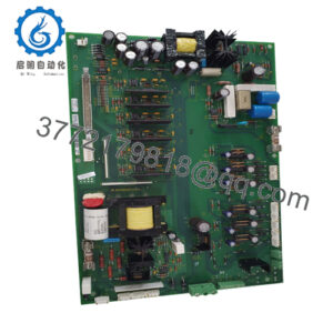
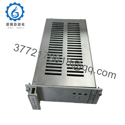
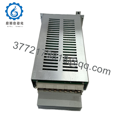
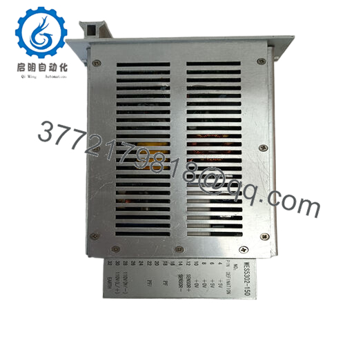
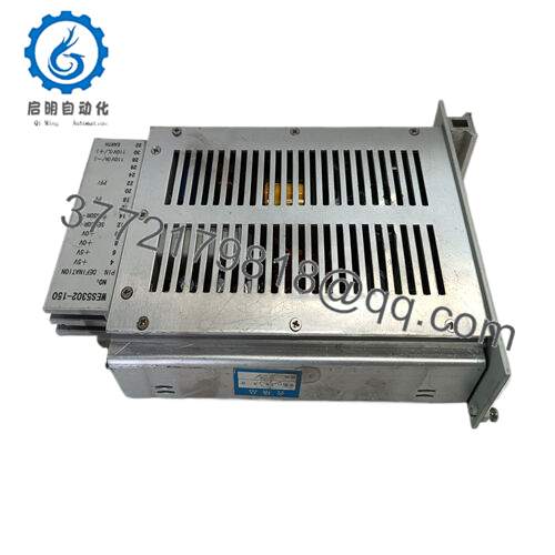
Product Model: GE WES5302-150
Product Brand: GE / GE Fanuc / WES line
Product Series: WES53xx / Digital Output / Field Controller family
Product Features:
- Optically isolated digital output board with 32 isolated outputs, designed for VMEbus systems
- Dual Eurocard board format with full address decoding and data logicSupports 8-bit and 16-bit data transmission, field-configurable pull-ups, and high isolation voltages
- Output current range 2.5 mA to 300 mA per channel, with isolation of 1,000 V continuous and up to 6,000 V pulses

- GE WES5302-150
Applications & Industry Context
In industrial control, where you have to send discrete digital signals reliably across noisy, harsh environments, the risk of ground loops, electromagnetic interference, cross-talk, and fault currents is high. A module like WES5302-150 addresses that by providing optically isolated digital outputs—i.e. each output channel is electrically decoupled from the VME bus and other channels. That isolation is especially critical in large control plants, turbine skids, wellhead stations, or wherever control signals drive relays, solenoids, or valves that might be remote or exposed.
For example, in an oil & gas wellhead control system, multiple valves, actuators, or safety shutdown devices need discrete control. The WES5302-150 can reliably drive those outputs while insulating them from noise or surges that might originate on the valve wiring or from lightning, switching, or other disturbances. The board is often used as part of a VME-based control rack, acting as the digital output interface to field devices.
It’s also useful in power plants, manufacturing lines, or process plants: wherever discrete control signals must be routed out, but you want protection and isolation. Because the outputs are optically coupled, even if one channel is exposed to a fault or surge, it is less likely to corrupt the rest of the control logic.
Furthermore, in retrofits or expansions of existing VME or GE / Fanuc control architectures, the WES5302-150 fits into standard slots and adds robust digital output capability without extensive rewiring.
Product Role & System Integration
WES5302-150 functions as a digital output interface board in a VME or modular control system. It resides in the rack, receives data or commands from a CPU or controller bus, and then drives external discrete outputs with isolation. Because of its design, one board can service many channels while maintaining electrical separation.
Mechanically, it’s built as a dual Eurocard module, meaning it fits into standard rack or chassis slots. Internally, the board includes address decoding logic, data path control, optocoupler arrays, and output drivers. It supports both 8-bit and 16-bit data width modes, so the system can choose how much data to send to the outputs in a given write operation.
From a system integration standpoint:
- The host CPU or controller writes to control registers or data registers on the WES5302-150 via the bus.
- The module decodes the address, latches the data, and activates the appropriate outputs.
- Because each output is optically isolated and isolated from the bus and from each other, the risk of fault propagation is minimized.
- Field wiring connects the outputs to relays, solenoids, lamps, or control valves, all through the isolated channels.
In designs that require both data and control redundancy or safety, multiple WES5302-150 boards might be used in parallel or with interlocks to ensure fail-over or safe shutdown behavior, though such usage depends on system architecture.
Technical Features & Benefits
Let’s unpack the key features and how they benefit a control system:
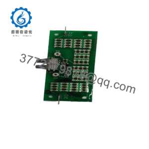
32 Optically Isolated Outputs
One of the standout features is the presence of 32 separate optically isolated outputs. Each output is isolated from the bus and each other, which helps contain faults.
Flexible Output Current Range
Each channel supports a wide current range—from 2.5 mA up to 300 mA, allowing versatility in driving smaller loads (indicator circuits) or more demanding loads (solenoids or valve coils).
The board provides high isolation: up to 1,000 V continuous isolation between the outputs and bus, and 6,000 V for pulses or transient events. That protects sensitive logic from surges.
Data Width / Transmission Modes
The module handles both 8-bit and 16-bit data writes. This allows the control system to map output words efficiently and support higher performance writes when needed.
Integrated logic handles address decoding to ensure correct mapping of output registers onto the bus memory space. That simplifies integration, since you don’t need extra external decoding hardware.
Modular / Dual Eurocard Format
Physically, it uses a dual Eurocard size, compatible with many rack systems and providing adequate area for connectors, isolation hardware, and heat dissipation.
Monitoring & Non-Privileged Data Paths
The board supports both regular (privileged) and monitoring data paths, meaning it may allow status monitoring of output states, fault flags, or internal diagnostics.
Field-Configurable Pull-Ups & Output Mode Options
The outputs have configurable pull-up resistors and possibly selectable mode (sink or source) to adapt to various load types. This flexibility is helpful when interfacing with different field devices.
Because of these features, WES5302-150 is robust, flexible, and able to support a wide range of digital output uses in harsh industrial settings.
Technical Specifications Table
Below is a table summarizing the key known and inferred specs of WES5302-150:
| Parameter | Specification / Detail |
|---|---|
| Model / Name | GE WES5302-150 |
| Function | Optically isolated digital output board |
| Number of Outputs | 32 isolated output channels |
| Output Current Range | 2.5 mA to 300 mA per channel |
| Isolation (Continuous) | Up to 1,000 V AC between output and bus |
| Isolation (Pulse / Transient) | Up to 6,000 V pulses |
| Data Width Support | 8-bit and 16-bit data transmission |
| Address / Control Logic | Internal decoding logic for mapping registers |
| Board Format | Dual Eurocard external size PC board |
| Output Voltage Levels | Up to ~30 V (voltage output range) |
| Operating Temperature | ~0 °C to +55 °C (based on source) |
| Storage Temperature | –20 °C to +85 °C |
| Other Features | Monitoring / non-privileged data paths, configurable pull-ups |
Installation & Maintenance Guidance
Based on practical experience with similar optically isolated digital output boards, here are recommended practices for WES5302-150:
Slot / Rack Integration
Ensure that the board is properly aligned in its rack slot, and that its backplane connectors mate fully with the system bus. Improper seating can lead to signal faults or open circuits.
Address & Bus Mapping
Confirm the address mapping, data width mode (8-bit vs 16-bit), and register mapping so that the host writes control data to the correct output registers. Mismatches here can lead to controlling wrong outputs or corruption.
Load Wiring & Output Protection
Because you may drive different loads (relays, solenoids, coils), ensure that the wiring observes proper gauge, shielding, and separation from high-current or noisy lines. Use flyback diodes (if driving inductive loads) to protect output circuitry.
Isolation Verification
During commissioning, verify output isolation using a megohmmeter or insulation tester. Ensure that no unintended leakage paths exist between the output and bus or between output channels.
Thermal / Ventilation
Although digital boards generally dissipate modest power, check for heating under full load (all outputs ON). If mounted in cabinets, ensure adequate ventilation, spacing, and airflow to avoid thermal stress.
Diagnostics & Fault Monitoring
If the board supports monitoring of outputs or internal status, leverage these diagnostics routinely. Use fault indicators or status registers to detect output failures or anomalies (e.g., open circuit, short circuit).
Periodic Testing & Maintenance
Periodically test outputs under load and check for consistent behavior. Inspect connectors and terminals for corrosion, loose contacts, or signs of overheating. Re-tighten screws or re-seat modules if intermittent behavior is observed.
Spare / Redundancy Strategy
Keep a spare WES5302-150 board (identical revision) in inventory, pre-configured if possible, to allow rapid replacement during maintenance windows with minimal interruption.
Lifetime / Aging Considerations
Optocoupler devices and output drivers can degrade over years, especially under heavy duty cycles or high temperature. Track output channel usage, and consider proactively replacing boards approaching known service life limits.