 WhatsApp: +86 16626708626
 Email:
  Phone: +86 16626708626
Description
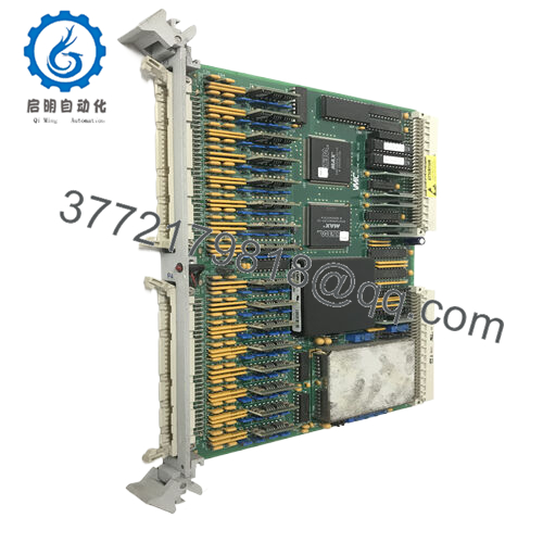
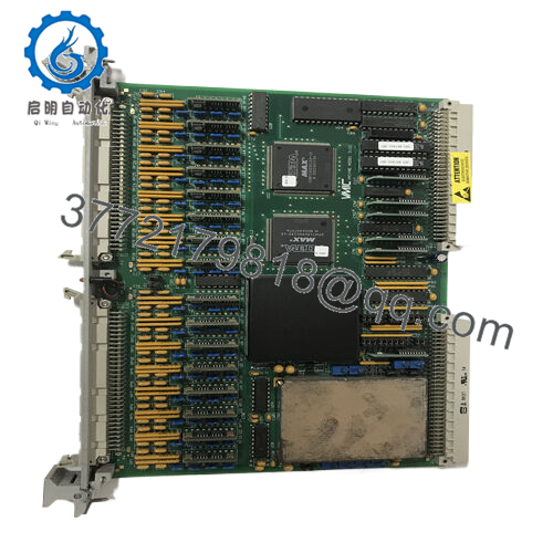
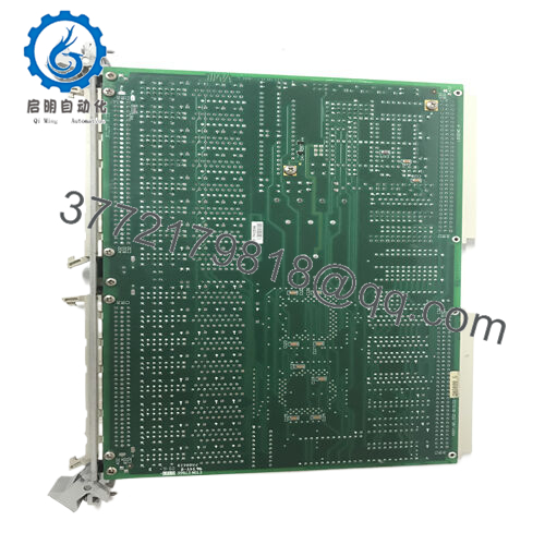
Product Model: GE VMIVME-3122
Product Brand: GE / VMIC / GE Fanuc
Product Series: VMIC VME Analog I/O
Product Features:
- 16-bit analog-to-digital scanning ADC with up to 64 channels in differential or single-ended configuration
- Selectable scanning rates (up to 100 kHz in high performance mode)
- Dual-ported buffer memory allowing simultaneous VME access and continuous data capture
- Flexible triggering modes (software, external, interval timer), channel gain programming, and optional low-pass filters
Applications & Context of Use
In industrial automation, process control, lab instrumentation, and data acquisition systems, you often need modules that constantly sample many analog signals (temperatures, pressures, flow transducers, strain gauges, etc.) and feed them into a control or monitoring backbone. The GE VMIVME-3122 is designed exactly for that — a VMEbus analog input board that digitizes up to 64 channels with high resolution and flexibility.
Consider a chemical processing plant: dozens of analog sensors (e.g. temperatures, pressures) need periodic scanning to feed control loops or trend analysis. A board like VMIVME-3122 enables continuous scanning in the background, freeing the host CPU to handle higher-level logic rather than tight analog polling. Because it supports differential inputs, it is well-suited to environments with long cable runs and electrical noise.
In power or utility substations, analog monitoring is equally critical — e.g. monitoring voltage, current, vibration, or environmental sensors. The VMIVME-3122 can fit directly into the VME control rack and feed live analog values into protection or diagnostic systems.
Another scenario is test or measurement racks used in R&D or QA labs, where you may need dynamic analog data capture across many channels. The flexibility of VMIVME-3122 enables burst scans, triggered sampling, or synchronized multi-board acquisition (up to 16 boards in sync)
Because this product is older, it is now in a Restricted Production Phase (RPP) as of November 5, 2008, meaning new development ceased and available units are from existing inventories. When planning deployments, you should account for spare stocking and eventual migration paths.

- VMIVME-3122
- VMIVME-3122
Product Role & System Fit
The VMIVME-3122 acts as an analog front-end interface between physical signals and the digital control system. Internally, it continuously scans selected analog channels, converts them to digital values, and stores them in a dual-ported memory buffer. The VME bus host can then read from that buffer asynchronously, without interfering with the scanning process
Because of its dual-ported memory, the analog scanning loop and the host VME access operate in parallel, reducing latency or conflicts. The host doesn’t need to manage channel multiplexing or sample scheduling itself — the VMIVME-3122 handles it.
When integrating into a system, the module plugs into a standard VMEbus backplane (6U form). It is assigned an address space for control registers, buffer memory, and status registers. The host’s software configures scanning modes, triggers, gains, and reads data. It fits well alongside other VME modules such as I/O controllers, communication modules, or CPUs.
In systems requiring synchronized sampling across multiple boards, VMIVME-3122 supports trigger propagation so that multiple cards can start scans simultaneously (bootstrapped across up to 16 boards) . That makes it a building block for distributed data acquisition systems where phase alignment is vital.
Because the board supports both single-ended and differential modes, and selectable gain x1 or x10 per channel, it is adaptable to a wide range of sensor types and system scales. It also supports multiple scan granularities (1, 8, 16, 32, 48, or 64 channel blocks) to tailor performance to load
Technical Features & Benefits
Let’s look at the key design attributes that make VMIVME-3122 valuable in embedded analog systems.
16-bit Resolution & High Dynamic Range
With 16-bit A/D conversion, the module provides high precision over a wide analog range. This resolution helps in applications requiring fine discrimination across analog signal changes (e.g. strain gauges, thermocouples)
Channel Count & Flexible Scanning
It supports up to 64 channels in differential or single-ended mode. The scanning architecture supports various block sizes, letting you trade off throughput and scanning granularity.
Select Scan Rate / Performance Modes
In its high-performance variant, the module supports sample rates up to 100 kHz. In its standard mode, the maximum is 50 kHz That lets system designers choose between throughput and stability.
Dual-Port Memory Buffer
One of the most useful features is the dual-ported buffer (with sizes up to 1024 words, organized as 16-word deep buffer × 64 channels) that the host can read at any time, independent of the ongoing analog scanning loop This design reduces contention and allows continuous analog acquisition.
Trigger Modes & Synchronization
Three trigger modes are supported: software-trigger, external-trigger (via P2), or interval-timer-trigger. You can also cascade triggers across multiple boards to synchronize sampling across a system The module can generate a trigger output to sync downstream modules.
Channel Gain & Range Flexibility
Each channel can be programmed for gain ×1 or ×10. Input ranges are selectable (e.g. ±2.5 V, ±5 V, ±10 V, 0–5 V, 0–10 V) via jumpers or configuration . This allows matching to very small or larger signals without needing external amplifiers.
Optional Filters & Input Protection
Low-pass input filtering (e.g. 10 Hz, 50 Hz, etc.) can be added to reduce noise in slow measurement systems. The input lines are also designed to tolerate overvoltage to a degree to protect analog front ends
Trigger / Interrupt Interface & Bus Modes
The module supports interrupts via bus interrupter logic (Midscan / Endscan flags) to alert the host when a buffer is filled or a scan event completes. It also supports addressing via A16, A24, or A32 VME modes depending on configuration.
Legacy & Lifecycle Status
Because VMIVME-3122 has entered a Restricted Production Phase (RPP), new production is limited, and the module is mainly supported from legacy stock or refurbishment sources
A field note: in one data acquisition rack in a water treatment plant, replacement of older analog multiplexers with VMIVME-3122 simplified wiring, improved sampling fidelity, and offloaded the host CPU from channel scanning logic tasks.
Technical Specifications Table
| Parameter | Specification / Detail |
|---|---|
| Module Model | GE VMIVME-3122 (various suffixes) |
| Function | High-performance analog input / ADC board for VMEbus |
| Analog Channels | Up to 64 channels (differential or single-ended) |
| Resolution | 16 bits |
| Sample Rate | Up to 100 kHz (high-performance mode); 50 kHz (standard) |
| Dual-ported Buffer | Up to 1024-word buffer (e.g. 16-word deep × 64) |
| Trigger Modes | Software, external, interval timer |
| Gain Settings | ×1 or ×10 per channel |
| Input Ranges | ±2.5 V, ±5 V, ±10 V, 0–5 V, 0–10 V |
| Low-pass Filter Option | Yes, selectable filter options (10 Hz, 50 Hz, etc.) |
| Synchronization | Supports synchronized scanning across boards (up to 16) |
| VME Address Modes | Supports A16, A24, A32 modes |
| Interrupt / Bus Interrupter | Midscan / Endscan flags, IRQ support |
| Status / Lifecycle | Restricted Production Phase (RPP) since 2008 |
Installation & Maintenance Insights
From experience with analogous VME analog modules, here are recommendations when deploying VMIVME-3122.
Slot & Backplane Configuration
- Ensure your VME chassis and backplane support standard 6U board spacing and proper P2 user lines for analog signal routing.
- Assign base address and address decoding (A16 / A24 / A32) properly to avoid conflicts with other modules.
Signal Conditioning & Front-End Wiring
- Depending on whether using differential or single-ended mode, route and shield analog signal wiring accordingly. Differential inputs are preferable for long cable runs in noisy environments.
- Ensure bypassing or filtering of sensor leads near power cables or heavy motors to reduce noise pickup.
Gain and Range Setup
- Decide appropriate input ranges per channel and set them via configuration (software or hardware) early in setup.
- Use ×10 gain for small signals, but confirm that noise doesn’t dominate.
- If filters are used, check trade-offs between noise reduction and response speed.
Trigger & Synchronization
- If your system uses external triggers, verify signal timing integrity and jitter.
- For multi-board sync, test that trigger propagation yields synchronous sampling across all modules.
Buffer & Data Readout Strategy
- Poll or interrupt host software on Midscan/Endscan flags to ensure reading of buffer before overflow.
- If scanning at high rates (e.g. 100 kHz), be sure your host side can read memory fast enough to avoid data loss.
Thermal / Power Considerations
- Though analog boards typically consume modest power, verify that slot power and cooling are adequate.
- Avoid crowding high-heat modules adjacent if possible — maintain airflow.
Routine Validation & Diagnostics
- At commissioning, feed known reference voltages to each channel and verify correct conversion and scaling.
- Monitor for drift or offset over time — drift may indicate aging components or temperature shifts.
- Use the built-in interrupt and scanning flags to catch unexpected behavior or buffer overflows.
Spare & Lifecycle Planning
- Since the module is in RPP status, maintain spare boards in inventory.
- Consider migrating to newer analog input boards in future system overhauls — plan for mapping torque conversion and differential inputs.
Burn-In & Degradation Testing
- If possible, run a burn-in under nominal operation (scan cycles, temperature variation) for several hours or days after installation.
- Log error counts or dropped samples to detect marginal parts early.