 WhatsApp: +86 16626708626
 Email:
  Phone: +86 16626708626
Description
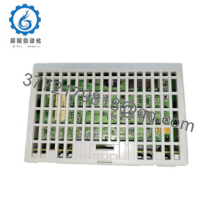
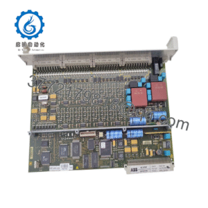
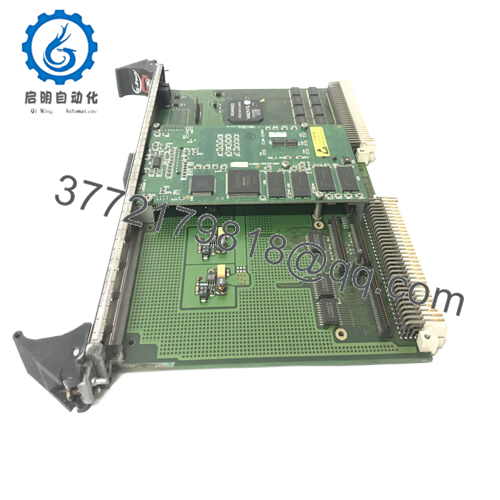
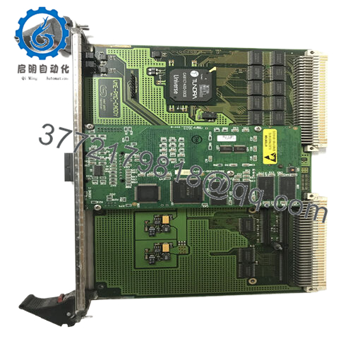
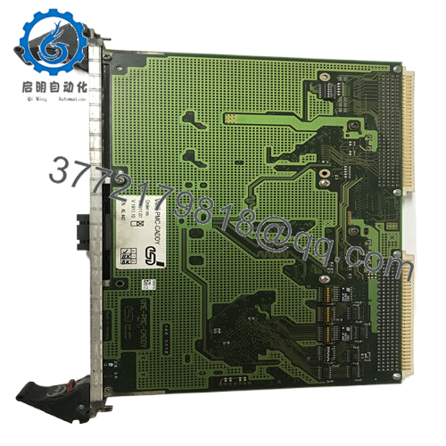
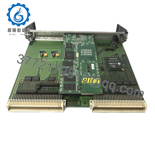
Product Model: GE VME-PMC-CADDY
Product Brand: GE (or Abaco / GE Embedded Systems)
Product Series: VME Carrier / PMC Bridge
Product Features:
- Serves as a VMEbus carrier board to host up to two PMC modules or one double-width PMC
- Employs a high-performance VME-PCI bridge such as Tundra UNIVERSE II (CA91C142) to link VME and PCI domains
- Routes PMC I/O through the VMEbus P2 connector (rear I/O path) for wiring convenience
- Compatible with IEEE P1386 standard for PMC modules, supports VME64 / VME64x features, and offers master/slave modes on VMEbus
Product Role & System Fit
When you insert a GE VME-PMC-CADDY into a VME chassis, you are effectively giving that chassis the ability to host PMC mezzanine modules. In essence, it acts as a bridge or carrier: the VMEbus environment interfaces with PMC boards (which may carry I/O, DSP, communication, or custom logic).
In a control rack or embedded system, if the existing architecture is VME-based (for instance, in legacy DCS, turbine controllers, or industrial instrumentation), but you want to leverage modern PMC modules (for networking, signal processing, or extension I/O), the VME-PMC-CADDY is the plug-in interface to do that.
Because VME remains in many industrial systems, this kind of adapter enables a hybrid architecture: you maintain the VME chassis backbone while gaining access to newer PMC modules without rewiring the whole system.
In a modernization project, you might replace older VME I/O boards with PMC modules via this CADDY. The host controller or CPU module sees the PMC embedded modules via the VMEbus bridge, enabling incremental upgrades.
In systems where modular redundancy or hot swapping is desired, having a PMC carrier inside the VME slot allows faster replacement of functional modules, rather than having to rewire large I/O frames externally.
Applications & Industry Context
In sectors such as power generation, process control, oil & gas, aerospace, or defense, many installations continue to use VMEbus platforms (e.g. GE Mark series controllers, legacy DCS racks). These systems often face pressure to upgrade or extend functionality—adding faster I/O, new communications, FPGA modules, or specialized PMC boards—without doing a full rip-and-replace.
The VME-PMC-CADDY is exactly the tool that helps bridge that gap. In a turbine control enclosure, for example, if you want to add a PMC-based ethernet interface or a high-speed data acquisition module, you can slip it into the VME-PMC-CADDY instead of redesigning wiring to an external PMC crate.
In test systems or lab setups that already use VME, the VME-PMC-CADDY lets engineers mix in PMC modules (e.g. FPGA I/O, ADC/DAC, network cards) without shifting the entire architecture.
Upgrades in substations or utility control rooms frequently use such carriers to inject new functionality into older racks with minimal physical changes.
Because this kind of module is standard in the industrial embedded world (VME + PMC), system integrators often favor it for bridging old and new technology domains.

- VME-PMC-CADDY
- VME-PMC-CADDY
Technical Features & Benefits
Let’s walk through the key strengths and technical elements of GE VME-PMC-CADDY:
PMC Hosting Capability
- The board supports two single-width PMC modules, or one double-width PMC module.
- PMC modules are installed into slots on the carrier; their I/O signals can be routed outward (especially via P2 of the VMEbus) for external connectivity.
VME-PCI Bridge & Bus Interface
- A key chip used is the Tundra UNIVERSE II CA91C142 VME-PCI bridge (or equivalent) to manage communications between the PMC modules (on PCI side) and the VMEbus.
- The board supports 32-bit VME data widths and 32-bit address lines (A32/D32).
- It can operate as either a VME bus master or slave, allowing flexibility in system architectures.
- A 4-level VME arbiter is supported for resource arbitration when operating as a master
I/O Routing / Signal Connectivity
- PMC I/O signals are typically routed to the VMEbus P2 connector (rear I/O), enabling wiring from the backplane rather than front connectors, which simplifies cabling.
- Different P2 pinout options exist: the default and an alternate “–32P2” pinout that allows more flexible or dual module I/O mapping.
- The front panel provides knockouts or pass-through openings for the I/O connector panels of installed PMC modules; blank covers are used if a slot is empty.
Standards & Compatibility
- The design aligns with IEEE P1386 (PMC standard) and VMEbus / VME64 / VME64x requirements.
- It supports standard dimensions (6U Eurocard form factor) to fit into VME chassis.
- It is engineered for industrial environments, with attention to cooling, power consumption, and layout for stable operation.
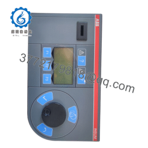
Diagnostics & Indicators
- On the front panel, LED indicators typically show VMEbus access or interrupts (yellow/red) to help diagnose activity or fault states.
- The carrier’s design often includes status feedback to detect bus errors or improper module installation. (Implicit in vendor descriptions)
Because of these features, GE VME-PMC-CADDY offers a flexible, modular path to expand VME systems with PMC modules, while minimizing rewiring and system upheaval.
Technical Specifications Table
Here is a spec summary based on available vendor information (to be confirmed via OEM datasheet):
| Parameter | Specification / Detail |
|---|---|
| Model / Name | GE VME-PMC-CADDY (or variants) |
| Bus Standard | VMEbus (VME64 / VME64x compatible) |
| PMC Slots | 2 × single-width PMC, or 1 × double-width PMC |
| Bridge Chip | Tundra UNIVERSE II CA91C142 (or equivalent) |
| VME Address / Data | A32 / D32 (32-bit address, 32-bit data) |
| Master / Slave Mode | Supports both master and slave operation |
| VMEbus Interrupts | Support on any of 7 IRQ lines |
| Front LED Indicators | For VME interrupt and bus access |
| P2 I/O Routing | Routed PMC I/O to VME P2 connectors |
| Alternate P2 Pinouts | Option “–32P2” variant supports alternate PMC I/O mapping |
| Form Factor | VME 6U Eurocard (fits standard VME chassis) |
| Operating Temperature | Industrial grade (vendor-dependent) |
| Power & Cooling | Designed for low power and efficient cooling |
| Standards | IEEE P1386 (PMC), IEEE 1014 Rev D (VME) compatibility |
Installation & Maintenance Insights
From my experience with similar carrier and interface modules, here are best practices and cautions when deploying VME-PMC-CADDY.
Slot Compatibility & Backplane
- Ensure your VME chassis and backplane support VME64 or the required bus width and signal routing.
- Be cautious about slot spacing and mechanical alignment—push the CADDY fully into its VME slot before securing mounting fasteners.
PMC Module Installation
- Insert PMC modules into the CADDY’s PMC slots carefully, aligning keys and connectors. Use the proper torque on retention screws.
- If only one PMC slot is used (or one double-width module), blank covers should be used for empty slots to maintain airflow and prevent dust ingress.
I/O Cable Routing & P2 Wiring
- Use the P2 connector on the VMEbus for PMC module I/O routing. Ensure the pin mapping (standard or –32P2 variant) matches the wiring harnesses.
- Shielding and proper cable routing are essential to maintain signal integrity, especially in noisy industrial environments.
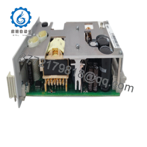
Power & Thermal Management
- Verify that your VME chassis power supply can support the combined load of the CADDY plus installed PMC modules.
- Leave sufficient ventilation; avoid installing high-heat modules adjacent without spacing.
Diagnostics & Validation
- After power-up, verify that the VMEbus acknowledges the CADDY and the installed PMC modules.
- Use indicator LEDs (bus access, interrupt) to confirm activity and detect faults.
- Run a test pattern or diagnostics on each PMC module through the bridge to validate data paths.
Firmware / Bridge Configuration
- Ensure that any firmware in the bridge (e.g. Universe II) is compatible with your host system or OS.
- For more complex installations, mapping of address spaces (VME → PMC) and interrupt routing must be configured correctly.
Periodic Maintenance
- Inspect connectors, seating, dust accumulation, and thermal performance periodically.
- Reseat modules or connectors if you detect intermittent behavior or marginal signals.
- Backup any configuration, address maps, or module assignments so you can restore after swaps quickly.
Spare / Hot Swap Strategy
- Where downtime is expensive, keep a fully programmed spare CADDY (with matching firmware, configuration) on hand.
- Replacement is often quick since the PMC modules can be moved from old to new CADDY, or swapped in place if design supports hot swap.