

 WhatsApp: +86 16626708626
 Email:
  Phone: +86 16626708626
Description
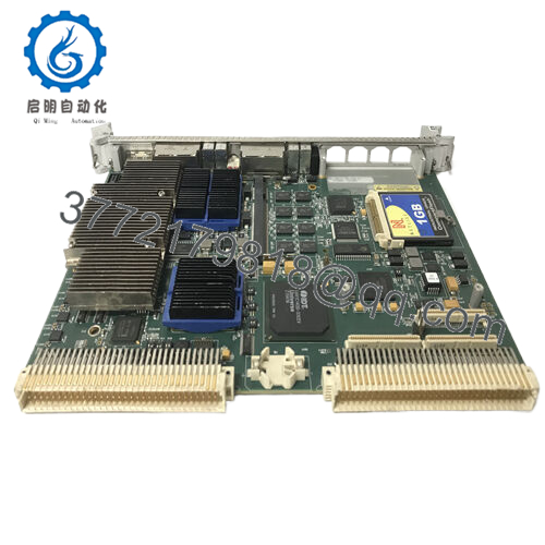
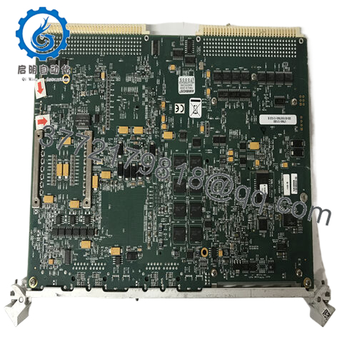
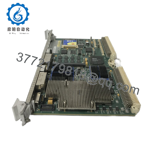
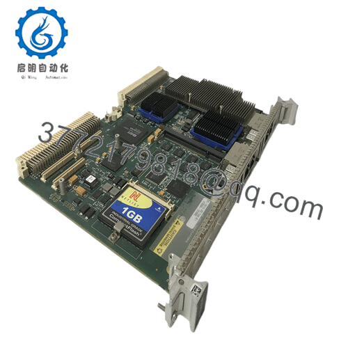
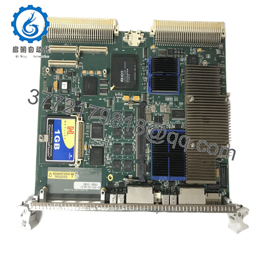
Product Model: GE V7668A-1310B0 / 350-931007668-131020 B
Product Brand: GE / VMIC line
Product Series: V7668A Control / Interface Modules
Product Features:
- High-resolution interpolation electronics, boosting internal output resolution (up to 16× multiplication)
- Compact “L15” form factor with all-metal housing, sealed bearings, and rugged design for industrial deployment
- Supports up to ~162,560 counts (via quadrature detection) on standard control systems
- Designed for applications requiring precision, repeatability, and real-time control (robotics, semiconductor, motion systems)

- V7668A-1310B0 350-9310007668-131020 B
Applications & Industry Context
Precision and reliability are non-negotiable in motion systems, robotics, semiconductor manufacturing, or high-accuracy industrial automation. Modules like V7668A-1310B0 / 350-9310-7668-131020 B often serve as core interpolation or encoder interface modules inside motion control loops.
Consider a lithography stage in a semiconductor tool: positioning must be repeatable to sub-micron tolerances. The built-in interpolation in the V7668A module, multiplying internal counts up to 16× without degrading accuracy, helps bridge between coarse encoder resolution and fine positional demands .
Similarly, in industrial robotics, where multiple axes move in coordinated space, modules like this ensure the control system “sees” smooth position feedback with minimal quantization error. In machine frameworks with tight size and weight constraints (e.g. pick-and-place heads, gantries), the compact “L15” style package is a practical advantage
Retrofitting older control systems is another common use case: replacing a lower-resolution encoder interface or analog position card with the V7668A gives more headroom for future upgrades without rewiring. And in clean environments or vacuum systems (e.g. semiconductor, metrology), the solid-metal, sealed design helps protect against contaminants or outgassing concerns.
In distribution automation or power plant control zones, this module might act as a part of closed-loop valve or damper positioning systems, providing more fine resolution and stability than legacy modules would allow. Its ability to plug into existing control architectures (e.g. quadrature support, industrial controllers) helps in bridging old and new.
Product Role & System Fit
The GE V7668A-1310B0 / 350-9310-7668-131020 B acts as a high-precision interpolation / encoder interface card within a broader control system. It’s not a general-purpose PLC, but rather a specialized module that takes in encoder signals (or position feedback) and presents a refined, multiplied count stream to control logic, counters, or motion controllers.
Internally, it uses rugged interpolation electronics to boost the resolution of the raw encoder signals. For example, if the physical encoder supplies N pulses per revolution, the V7668A may internally increase that up to 16× (via multiplication) while maintaining or even improving effective accuracy . This extra “granularity” is especially useful when the control logic or counting hardware supports only limited resolution by itself.
To the rest of the system, the module appears as a quadrature pulse source delivering higher count density. Many PLCs, counters, motion controllers, or FPGA input cards can accept such quadrature inputs and interpret high-count streams. The module’s engineering ensures that even under demanding speed or torque conditions, the output remains stable and jitter minimal.
Physically, the module fits a compact “L15” form factor (a servo-mount style packaging) with sealed bearings and all-metal housing for durability and vibration resistance . This enables it to be mounted close to the encoder or inside machine enclosures, reducing cable length, signal degradation, or noise pickup.
Because V7668A-1310B0 inherits a design intended to support significant resolution (e.g. up to ~162,560 counts in standard systems via quadrature support) it is a practical interface upgrade path for systems that need more positional fidelity without replacing the entire control logic stack.
Technical Features & Benefits
Let’s examine what makes GE V7668A-1310B0 / 350-9310-7668-131020 B compelling for high-end control systems:
High-Resolution Interpolation
One core strength is its ability to multiply encoder pulses internally. The module supports up to 16× interpolation internally, increasing output resolution while preserving the underlying accuracy limits of the encoder system For standard quadrature detection, count stream outputs can reach ~162,560 counts, offering fine-grained feedback to controllers
Compact L15 Form Factor
The “L15” style packaging is compact and servo-mountable. That reduces installation footprint, allows proximity mounting to encoder shafts (cutting down cable length), and helps in constrained machine spaces. The module is encased in all-metal construction with sealed double bearings to sustain vibration and mechanical stress over time
Durability & Rugged Design
Given its industrial intent, the module’s hardened electronics, sealed design, and robust mechanical structure help it survive factory-floor stress: vibration, temperature swings, EMI interference, and mechanical shock. The all-metal housing also helps in heat dissipation and electromagnetic shielding.
Noise Rejection & Signal Integrity
Because encoder signals (especially from high-speed or long cables) are susceptible to noise, the interpolation electronics in the V7668A module likely include filtering, edge shaping, and error detection to maintain stable outputs. This ensures that controller inputs aren’t fed with jitter or spurious pulses.
Multiplication Without Loss of Accuracy
One risk in interpolation is that coarse noise or nonlinearity can be amplified. The design in the V7668A-1310B0 is intended to preserve the baseline encoder accuracy while increasing output density. In practice, this means that downstream control logic can take advantage of finer resolution without needing to upgrade the encoder itself.
Broad Compatibility
Because many PLCs, counters, and motion controllers accept quadrature or incremental pulse streams, V7668A-1310B0 is designed to interface cleanly with existing hardware. No exotic protocols or interfaces—just a clean, high-count pulse output that conventional control hardware can interpret.
Upgrade Path & Integration Ease
For users upgrading older systems, inserting the V7668A module can allow you to preserve encoder hardware, control boards, wiring, and logic, while improving resolution and performance. This modular upgrade path is often more economical than wholesale replacement.
An illustrative example: In a machine tool retrofit, one OEM replaced a lower-resolution analog servo feedback module with the V7668A. Immediately, the servo controller gained finer position feedback and smoother motion, reducing vibration and improving surface finish, with no changes to the main controller.
Installation & Maintenance Insights
From hands-on experience (and general best practices for interpolation/encoder modules), here are recommendations and caution points when deploying V7668A-1310B0 / 350-9310-7668-131020 B.
Mounting & Proximity to Encoder
Whenever possible, mount the interpolation module close to the encoder (within the same enclosure or mounting bracket). Shorter wiring helps reduce noise, signal degradation, and phase skew. Use the at-hand L15 mounting format to anchor it rigidly, avoiding relay of vibration from connected hardware.
Cable Routing & Shielding
Encoder signal cables should be shielded, twisted-pair, and routed away from power cables or motors. Proper grounding of the shield (preferably at one end) is essential to avoid ground loops or induced noise. Keep cable bends gentle, avoid sharp corners, and maintain consistent cable lengths for differential pairs to minimize delay imbalance.
Power & Signal Integrity
Provide stable, clean power to the module (within its specified voltage range). Voltage transients or ripple can negatively affect interpolation electronics. If the module accepts multiple power sources, maintain redundant or filtered supplies in environments with transient loads.
Testing & Calibration
During commissioning, validate the raw encoder signal first (without interpolation) to confirm pulselines, direction, and phase alignment. Then enable the module’s interpolation functions and test incremental output. Use known positional steps or calibration tools to verify linearity and absence of anomalies. Monitor for missing pulses or jitter under high-speed motion.
Thermal & Ventilation Considerations
Although compact, the module may dissipate heat, especially under high-frequency operation. Ensure enclosure ventilation or heat sinking is adequate. Avoid placing heat-emitting neighbors too close. Periodic temperature checks during early operation can reveal hotspots or ventilation deficits.
Diagnostics & Monitoring
If the module has onboard status indicators or diagnostic bits (e.g. fault LEDs, error flags), monitor them routinely. Marginal conditions (rising error or fault counts) can precede failures. Log these statistics during initial run-in periods.
Spare / Replacement Strategy
Keep a matched spare V7668A-1310B0 / 350-9310-7668-131020 B module (same firmware / revision) on hand. Because the module likely has minimal configuration beyond wiring, swap-in times are low. Pre-test the spare to avoid surprises when needed.
Burn-In & Stress Testing
Before committing to production, subject the module to extended cyclic tests, vibration excitation (if your environment travels or vibrates), thermal cycles, and high-speed motion simulation. Detect early failures or marginal behavior and burn them in before deployment.


