


 WhatsApp: +86 16626708626
 Email:
  Phone: +86 16626708626
Description
Product Model: GE SR745-W2-P1-G1-HI-A-L-R-E
Product Brand: GE (Multilin / Power Management)
Product Series: 745 Transformer Protection Series
Product Features:
- Comprehensive protection functions: differential, overcurrent, over/under voltage, frequency, and thermal monitoring
- FlexLogic™ customizable logic integrated for advanced control
- Multi-protocol communications (Ethernet, RS-232/RS-485, etc.), SCADA / DCS ready
- Rugged design supporting wide temperature, galvanic isolation, fault diagnostics

- SR745-W2-P1-G1-HI-A-L-R-E
Product Role & System Fit
When you drop a GE SR745-W2-P1-G1-HI-A-L-R-E relay into a substation or plant environment, you are placing an advanced protection and control node right at the heart of transformer oversight. This is not a mere sensor interface — it is a multifunctional protection, monitoring, and control device, bridging the transformer’s electrical signals to higher-level SCADA, DCS, or station automation systems.
In typical power architectures, the SR745 acts as the transformer’s “brains.” It supervises primary windings, secondary windings, neutral configurations, and monitors fault conditions like internal winding short circuits or external overcurrents. It sits between the transformer’s CT (current transformer) and VT (voltage transformer) inputs and the substation control network. Upstream, it exchanges data, alarms, and control commands with SCADA or protection schemes via Ethernet or serial channels. Downstream, it drives trip circuits, alarms, and logic outputs.
One major strength of GE SR745-W2-P1-G1-HI-A-L-R-E is its interoperability. It supports multiple protocols (e.g. Modbus, IEC 61850, DNP) so that it can slot into legacy or newer networks. If you are adding it to an existing bay, it can coexist with older relays and communicate with a mix of substation controllers. Because it supports flexible logic (FlexLogic™), you can embed site-specific behaviors — for example, conditional tripping or load shedding — without needing an external PLC.
In retrofit projects, many engineers choose SR745-W2-P1-G1-HI-A-L-R-E because it gives you modern diagnostics and network features while retaining compatibility with existing CT/VT wiring. It becomes the upgrade piece without upheaval of the full protection scheme.
Applications & Industry Context
Across power plants, distribution networks, industrial plants, and utility substations, transformers are among the most critical assets in the electrical chain. A transformer failure is costly — both in direct repair cost and the lost downtime or ripple effects in the grid. That is why you need a smart transformer protection relay like the GE SR745-W2-P1-G1-HI-A-L-R-E to detect early anomalies and isolate faults fast.
In a hydroelectric plant, for example, you might have step-up transformers feeding high-voltage transmission lines. The SR745 monitors differential currents, overexcitation, overfluxing, and thermal stress. If an incipient winding short begins, the differential algorithm in SR745-W2-P1-G1-HI-A-L-R-E will detect imbalance and trip instantaneously — often isolating before collateral damage.
In oil & gas or petrochemical complexes with large onsite generation, site transformers often see variable loads, harmonic distortion, and inrush currents. In those environments, the ability to discriminate inrush (during energization) vs. fault currents is essential. The SR745-W2-P1-G1-HI-A-L-R-E supports inrush masking or harmonic restraint techniques to avoid nuisance tripping.
Infrastructure zones—like a data center or hospital—must maintain continuous supply. A relay failure or false trip could cascade. In that context, the SR745-W2-P1-G1-HI-A-L-R-E enables redundancy, hot backup, and configurable logic so you can tune protective actions precisely.
Finally, in utility distribution, the relay helps with asset management. The diagnostic logs, waveform capture, and event records help engineers assess transformer health, aging trends, or emerging insulation deterioration — enabling predictive maintenance rather than reactive repair.
Technical Features & Benefits
The GE SR745-W2-P1-G1-HI-A-L-R-E is packed with features that make it a robust, flexible, and future-proof solution. Let’s walk through core highlights and how they translate to value on the ground.
Protection Suite & Algorithms
At its heart, SR745 supports differential protection, overcurrent (phase, neutral), over/under voltage, frequency elements, overexcitation, and thermal overload functions. The differential element can detect internal faults down to microsecond precision, ensuring fast isolation. Overfluxing detection helps prevent transformer core saturation or overheating under overexcitation. These layers defend the transformer from internal winding shorts, external faults, or abnormal operating stress.
FlexLogic™ & Custom Logic
One key differentiator: the built-in FlexLogic engine lets you build conditional logic, interlocks, custom alarms, and sequencing without an external PLC. For example, you could define logic that delays tripping under certain startup inrush conditions, or inhibit alarms during maintenance windows. Because logic lives in the SR745, fewer external devices are needed — simplifies architecture and reduces points of failure.
Communications & Integration
The SR745-W2-P1-G1-HI-A-L-R-E supports multiple communications channels — Ethernet (TCP/IP), serial (RS-232, RS-485), and sometimes IEC 61850 or Modbus. This flexibility lets you integrate it into both modern IEC 61850 substation systems or legacy DCS/SCADA networks. It also supports remote firmware updates, remote diagnostics, and configuration tools, making life easier for engineers doing commissioning or field support.
Diagnostics, Logging & Event Capture
The relay includes high-resolution oscillography (waveform capture) for faults, inrush events, or abnormal disturbance sequences. It stores event records with timestamps, making postmortem analysis possible. Alarms, status changes, and internal self-tests are logged as well. With these, you can see trends (e.g. incremental leakage, thermal drift) before a trip becomes necessary.
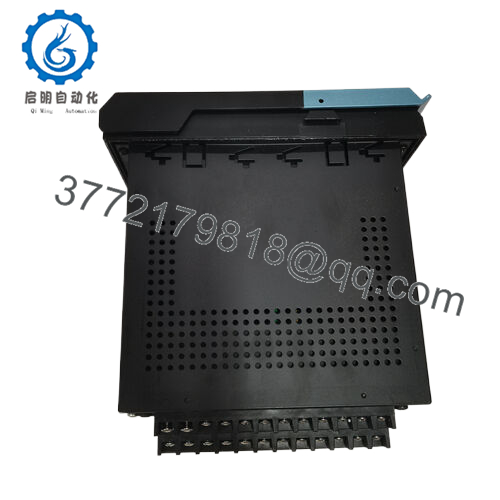
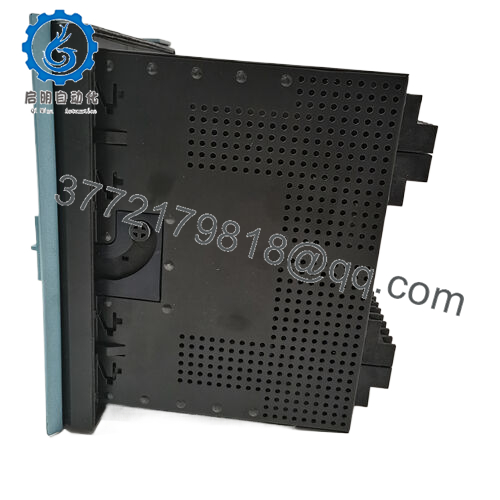
Robust Design & Environmental Tolerance
GE has engineered the SR745 line to survive harsh substation environments. SR745-W2-P1-G1-HI-A-L-R-E is designed with galvanic isolation between signals and power, electromagnetic interference (EMI/RFI) suppression, and wide temperature operation (typical ranges include –40 °C to +70 °C). The enclosure, chassis, and internal construction are built to endure vibration, humidity, and transients. These protections ensure stability in realistic field environments.
Redundancy & Failover Capabilities
In mission-critical or utility settings, you can configure the SR745-W2-P1-G1-HI-A-L-R-E in redundant architectures. Dual-relay hot standby configurations allow seamless takeover if the active unit fails. Network redundancy (dual Ethernet paths) ensures communications survive switch or link faults. This greatly improves availability.
Ease of Use & Operator Interaction
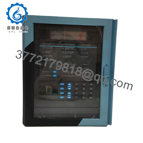
Front panel display often supports a multi-line LCD (e.g. 40 characters) and extended keypad, enabling operators to view real-time data, alarms, and navigate menus. During commissioning, the display and interface help validate setpoints or diagnose issues without needing to hook up a PC. That ease of access reduces field errors.
A field example: in a 132 kV substation, after swapping in a SR745-W2-P1-G1-HI-A-L-R-E, the maintenance crew appreciated that the trip logic could be tested offline via FlexLogic without triggering actual breaker operations — saving hours of safe-out switching.
Installation & Maintenance Insights
Even a powerful protection relay like GE SR745-W2-P1-G1-HI-A-L-R-E must be installed thoughtfully, or you invite avoidable faults. Here are best practices and tips drawn from field experience:
Mounting & Ventilation
Mount the module on a well-ventilated panel or enclosure panel that allows airflow. Leave clearance on sides and above (for example, 20 mm) to avoid trapping heat. Avoid placing heat sources directly adjacent. Make sure the relay is not in a zone of direct radiant heating or near cable bundles generating heat.
Grounding & Shielding
Proper grounding is critical. The relay chassis should be grounded to protective earth. Signal cables, CT/VT wiring, and communication cables should be shielded and grounded at one point (usually the relay end) to avoid ground loops or noise pickup. Use twisted pair and quality shielded cables, and keep power and signal runs separate when possible.
Power Supply & Surge Protection
Use a well-regulated DC supply (commonly 24 V DC) with margin headroom for surge and inrush. Consider adding surge arrestors or transient suppressors to the DC bus. Input filtering (EMI filters) helps suppress noise from nearby switchgear or transformers.
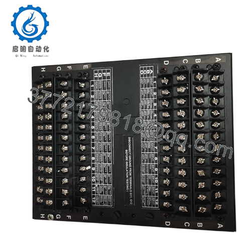
CT/VT Wiring & Polarity
Observe correct CT and VT wiring polarity (phase relationships, excitation, wiring loops). Ensure proper burden limits, avoid CT saturation, and ensure CT secondaries are shorted when relay is disconnected. Improper wiring can lead to false differential picks or instability in protection.
Commissioning Strategy
Start with a clean configuration (disable logic/tripping), validate sensor inputs (CT/VT ratios, signal levels), then step through protection function tests individually (using secondary injection). Use internal test modes, simulate fault waveforms, and enable trip logic only after verifying thresholds. Record baseline values and event signatures for future reference.
Firmware & Configuration Backups
Always keep a current firmware version and maintain backups of configuration settings. Prior to any firmware upgrade, test in a simulated environment. Use the relay’s remote procedure capabilities for firmware loading and configuration management to minimize site visits.
Routine Maintenance & Diagnostics
Set a schedule (e.g. annually) to check connectors, ensure no corrosion or dust build-up, reseat terminals if needed, and validate signal integrity. Monitor internal diagnostic logs for warnings or margin drifts. Exercise backup logic or redundancy periodically to confirm failover paths work.
Spare Parts & Hot Standby
It is wise to keep a matched spare of SR745-W2-P1-G1-HI-A-L-R-E (with same firmware revision) in inventory. In critical installations, maintain hot standby or “advance replacement” agreements so you can swap in quickly with minimal downtime.
Technical Specifications Table
| Parameter | Specification / Detail |
|---|---|
| Protection Functions | Differential (transformer), overcurrent (phase & neutral), over/under voltage, frequency, overexcitation, thermal supervision |
| Logic Engine | FlexLogic™ — user programmable logic, interlocks, custom control |
| Communication Interfaces | Ethernet TCP/IP, RS-232, RS-485, optional IEC 61850 or Modbus |
| Relay Outputs / Inputs | Multiple binary outputs (trip, alarm), binary inputs, auxiliary logic I/O |
| Measurement Inputs | CT inputs (phase, neutral), VT inputs, auxiliary analog inputs |
| Display & Interface | Multi-line LCD (e.g. 40-character), extended keypad, LED indicators |
| Operating Temperature Range | –40 °C to +70 °C (typical) |
| Power Supply | 24 V DC (commonly with ±10% tolerance) |
| Isolation | Galvanic isolation between input/output, internal protection |
| Event / Waveform Capture | High-speed oscillography, event recorder (timestamped) |
| Redundancy Support | Hot standby, dual Ethernet paths, dual power feeds |
| Certifications | Designed to utility / substation standards (e.g. relevant IEEE / IEC protection norms) |
| MTBF / Reliability | High reliability design, typical >100,000 hours (vendor dependent) |
Related Models (with differences)
- SR745-W2-P0-G1-HI-A-L-R-E — same protection functions but without dual-winding support
- SR745-W1-P1-G1-HI-A-L-R-E — single-core transformer version
- SR745-W2-P1-G1-HI-A-L-T-E — includes enhanced temperature or thermal tracking features
- SR745-W2-P1-G1-HI-A-L-R (no ‘E’) — base version without extended communications add-ons
- SR745-W2-P1-G1-HI-A-L-R-H — variant with higher current/voltage ratings
- SR745-W2-P1-G1-HI-A-L-R-I — version tailored for international grid standards
Each variant adjusts parameter coverage: some omit layers (e.g. dual-winding protection), others extend with extra communication or auxiliary functionality.


