


 WhatsApp: +86 16626708626
 Email:
  Phone: +86 16626708626
Description
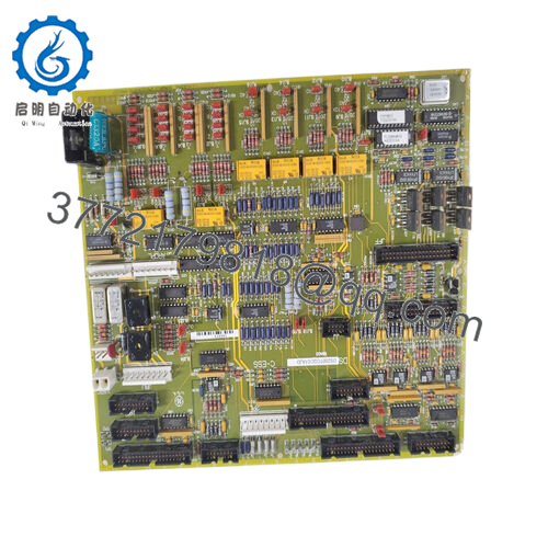
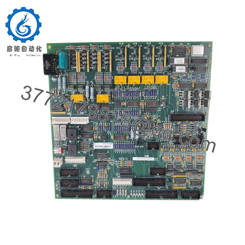
Product Model: GE DS200TCQCG1AJD
- Product Brand / Series: GE / GE Mark V / DS200 series
- Module Type: Analog / I/O expansion / RST overflow board
- Product Features:
• Provides expanded analog I/O channels in GE Mark V / turbine control systems
• Configurable via hardware jumpers (24 jumpers) for signal ranges, filtering, etc.
• Multiple connectors (40-pin, 34-pin, 16-pin) for interfacing with I/O cores and backplane
• Designed for use in redundant architectures (overflow / fault tolerance)

- DS200TCQCG1AJD
- DS200TCQCG1AJD
Applications & Industry Context
In turbine control systems, every sensor, actuator, and module must reliably interface with the core controller logic. The GE DS200TCQCG1AJD serves as an I/O expansion / overflow board within GE’s Mark V (DS200) architecture, particularly when the built-in I/O capacity is exhausted or when analog signal density requires extension. In practice, it is used in:
- Gas and steam turbine control rooms to support additional transducer channels, LVDTs (linear variable differential transformers), RTDs, analog sensors, and analog outputs.
- Power plants implementing GE Speedtronic / Mark V control, where redundancy and fail-safe operation are essential.
- Retrofit or extension projects: when existing DS200 I/O modules can’t accommodate new signals, the DS200TCQCG1AJD provides a plug-in expansion route without redesigning the entire system.
- Redundant control systems: used as a “overflow” board to balance I/O load or in backup configurations to take over if primary boards fail.
Because it plugs into the Mark V backplane and is understood by the control modules, this board becomes part of the deterministic signal path, ensuring that expanded analog inputs / outputs are processed with minimal latency and in lockstep with core control logic.
Technical Features & Benefits
Here are some of the key features and their advantages (drawn from supplier descriptions and analogous DS200 modules):
1. Hardware Jumper Configurability
This board includes 24 configurable jumpers that allow tailoring of analog signal ranges, filtering constants, excitation levels, or mode selections. This gives system engineers flexibility when integrating different sensor types or dealing with cable length differences.
2. Connectors & Signal Paths
It features multiple connectors:
- 3 × 40-pin (often named JFF, JE, 6PL) for primary I/O core interfacing.
- 3 × 34-pin connectors for additional I/O or signal routing.
- 1 × 16-pin connector (often called JC) for auxiliary tasks or control signaling.
Such connector diversity ensures the board can handle dense wiring architectures while maintaining clarity in signal routing.
3. Signal Processing Capability
The module processes analog inputs and outputs, converting raw signals from sensors (voltage, current, transducer signals) into data the main controller can interpret. It supports signal conditioning to reduce noise, maintain linearity, and preserve fidelity under industrial conditions.
Furthermore, it’s often used for excitation signals for LVDTs or other position sensors, which are critical in rotor positioning or valve actuation feedback loops.
4. Redundancy and Overflow Function
In high-availability or critical turbine systems, some modules act as overflow boards—that is, when the primary I/O modules fill up, this board takes on the excess load or stands ready to take over failed channels. Hence “RST overflow” is a descriptor sometimes seen in supplier listings.
By distributing I/O across primary and overflow modules, system reliability improves, and single-point overload risk is reduced.
5. Rugged Design & Industrial Suitability
The board is built for industrial environments. Speaker listings note standard industrial temperature ranges, conformal coating, and durable construction to resist ambient contaminants.
In some descriptions, it’s claimed to operate reliably from –40 °C to +85 °C (though such ranges may depend on variant or revision).
6. Seamless Integration in Mark V Ecosystem
Because it follows the GE DS200 / Mark V naming and connector standards, integration with core control modules, I/O cores, and diagnostics systems is generally plug-compatible. That reduces engineering effort during retrofits and module replacement.
Technical Specifications
Below is a summarized spec table—some values are based on supplier claims and analogous board references, so validate with GE documentation before use.
| Parameter | Value / Description |
|---|---|
| Model | GE DS200TCQCG1AJD |
| Series / Platform | GE Mark V / DS200 family |
| Function | Analog I/O expansion / RST overflow module |
| Hardware Configuration | 24 jumpers configurable |
| Connectors | 3 × 40-pin, 3 × 34-pin, 1 × 16-pin (JC) |
| Analog I/O Handling | Inputs / outputs from sensors / excitation lines (voltage/current) |
| Redundancy Support | Suitable for overflow / redundant architectures |
| Connector ID Tags | JFF, JE, 6PL (for 40-pin connectors) |
| Operating Temperature | Common supplier claims –40 °C to +85 °C (variant-dependent) |
| Power / Supply | Matches Mark V control voltage (often ±5 V, ±15 V from backplane) per system design |
| Signal Accuracy / Performance | High precision analog path, jumpers for filtering / scaling |
| Software / Control Integration | Handled by Mark V controllers; transparent to existing control logic |
Installation & Maintenance Insights
From field experience and module behaviors common to DS200 / Mark V expansions:
Installation Tips
- Align the board carefully in its backplane slot, ensuring connectors (JFF, JE, 6PL, JC) seat fully.
- Before powering, confirm jumper settings (24 jumpers) reflect expected sensor ranges, filtering, excitation levels, etc. Misconfigured jumpers are a common cause of analog drift or offset errors.
- Maintain good connector cleanliness—oxidation or debris can cause analog noise or loss of channels.
- Ensure proper grounding and shielding, especially for analog wiring (sensor leads, transducers).
- In redundant setups, mirror the jumper settings across mirrored boards to ensure symmetry.
Maintenance / Troubleshooting
- Use built-in diagnostics or logging from the Mark V controller to isolate channel failures or offsets.
- Compare analog readings against known calibrated sensors to detect drift or board degradation.
- If a module fails, replace with same part number and move over any calibration / offset values if possible.
- When handling the board, use ESD precautions and ensure power is off before reconfiguration.
- Inspect for signs of overheating, component discoloration, or connector pin bending, especially in high ambient environments.
Related / Alternative Modules
- DS200TCQCG1AHE – A variant (H/E revision) of the analog I/O expansion board (similar connector layout, jumper structure)
- DS200TCCBG1ALD, DS200TBCAG1A, DS200DTBAG1 – Other DS200 I/O or expansion modules often used in the same Mark V systems
- Primary DS200 I/O Core boards – The main analog / digital I/O cores in the Mark V system; this module sits behind them in the signal chain
- Modern replacement boards – In control system modernization projects, newer I/O expansion modules (from GE / Emerson / other turbine control OEMs) sometimes replace DS200 modules.


