 WhatsApp: +86 16626708626
 Email:
  Phone: +86 16626708626
Description
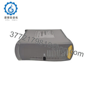
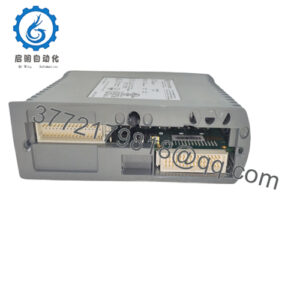
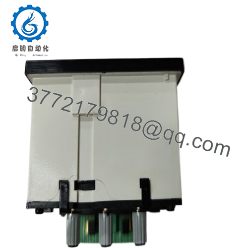
Product Model: EPQ96-2
Product Brand: DEIF
Product Series / Type: Electronic Potentiometer / Speed-Governor Interface
Product Features:
- Replaces traditional motor potentiometers; no moving parts, maintenance-free
- Converts relay output from PI controllers into analog, current, or PWM signals
- Supports CAN J1939 input for conversion to analogue or PWM outputs
- Offers manual/auto mode, preset memory, output span adjustments, and integration time settings
Applications & Industry Context
In many power generation, engine control, and automation systems, accurate speed or governor control often depends on a motor potentiometer. Traditional potentiometers with moving parts wear over time, leading to drift, maintenance, or failure. The DEIF EPQ96-2 replaces that mechanical component with a solid-state electronic potentiometer — offering reliability, precision, and longevity.
Originally developed for genset OEMs, hybrid plants, and marine engines, the EPQ96-2 plays a role in control systems where a PI controller issues on/off relay outputs, and those need conversion into analog or PWM signals for the engine’s electronic governor. The EPQ96-2 “translates” that relay logic into smooth control signals, ensuring stable speed regulation even under varying load.
In modern setups where CAN J1939 networks are used, it can directly accept CAN commands (e.g. TSC1 telegrams) and output the corresponding analog or PWM signal. This makes it a bridge between digital control and analog governors — especially in retrofits or hybrid systems.
Because it’s built without moving parts, the device finds use in harsh, abrasive, or vibration-rich environments — from generator enclosures to marine engine rooms. Many systems that once relied on mechanical potentiometers now use EPQ96-2 to reduce wear, drift, and routine servicing.
In short: EPQ96-2 is a smart, reliable interface component that maintains legacy analog control while supporting modern digital control strategies.

- EPQ96-2
Technical Specifications
Below is a summary of key specifications, drawn from its datasheet and user manual.
| Specification | Description / Value |
|---|---|
| Model | EPQ96-2 |
| Type | Electronic potentiometer / analog/PWM interface |
| Supply Voltage | 9 … 31.2 V DC (nominal 12–24 V) |
| Output Voltage / Current | –10 … 0 … +10 V or –20 … 0 … +20 mA (selectable) |
| Output Impedance | 500 Ω (used to convert current mode) |
| PWM Output | 0 … 6 V PWM at 500 Hz (±50 Hz) |
| Integrating Time (Slope) | 2.5…25 s (or ×5 factor: 12.5…125 s) |
| Preset / Memory Options | Memory of last output (“last”) or preset value at power-up |
| Inputs | Up, Down, Preset (digital inputs) 18…32 V DC |
| Relay Outputs | Auto / Manual mode indication, status output, and internal relay to isolate output on fault |
| CAN / J1939 Input | Accepts J1939 telegrams (e.g. TSC1) to control analog/PWM output |
| Operating Temperature | –10 … +55 °C nominal, –25 … +70 °C full range |
| Storage Temperature | –40 … +70 °C |
| Panel Cut-out / Housing | Front size 96 × 96 mm, cut-out 92 × 92 mm, flush mounting |
| Protection / Isolation | Supply to circuits: 500 V isolation; status relay circuits separately isolated |
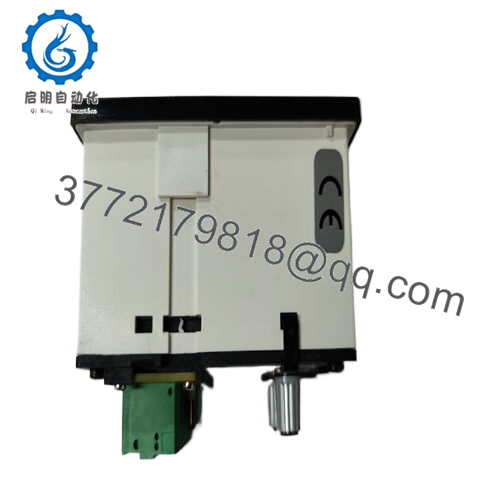
| Certifications | CE marking; meets industrial / marine application EMC & safety levels |
Technical Features & Benefits
Here are the standout features of EPQ96-2 and why they matter in real systems:
Zero Moving Parts = Maintenance-Free
Unlike mechanical potentiometers, the EPQ96-2 has no sliding contacts or wear-prone elements. That means lower drift, fewer adjustments, and longer service life.
Relay-to-Analog or PWM Conversion
Many PI controllers output relay contacts (on/off). The EPQ96-2 translates that into a smooth analog or PWM signal to drive electronic speed governors. That makes it a crucial interface in older or hybrid control schemes.
Dual Mode: Manual / Auto
It supports both manual mode (using front push-buttons) and automatic mode (driven by digital inputs or CAN). The ability to override and locally adjust gives flexibility, especially during commissioning or maintenance.
CAN J1939 Support
Modern engines and control systems often use CAN bus. The EPQ96-2 can accept J1939 telegrams and convert them into analog or PWM control signals — thereby functioning as a protocol bridge.
Preset / Memory Settings
After power interruptions, you can have the output resume at a preset value or the last known value. That behavior helps avoid sudden jumps in control output when the system restarts.
Fine Adjustment of Range & Slope
You can adjust min, max, and time constants to shape the control response. That flexibility helps match the EPQ96-2 to a wide variety of governors and engine dynamics.
Fault Isolation / Safe Output on Failure
In case of supply dropout or internal failure, the EPQ96-2 isolates the output and forces a defined fallback output (e.g. a shunt resistor output) to maintain control stability.
Installation & Maintenance Insights
To ensure the EPQ96-2 performs reliably, here are installation tips and maintenance best practices:
Panel Mounting & Cut-out
- The front of the device is 96 × 96 mm; the cut-out is 92 × 92 mm. Use clamps for secure flush mounting.
- Orientation matters: avoid positioning where the display is obstructed or frequently exposed to liquid drips.
Power and Grounding
- Supply the device with a stable DC voltage in the range 9–31.2 V DC.
- Ensure robust grounding and shielding — especially for analog or PWM lines — to minimize noise.
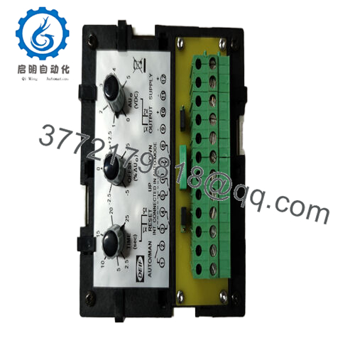
Wiring & Inputs / Outputs
- Up, Down, and Preset inputs: 18–32 V DC, galvanically separated.
- Relay outputs (Auto, Status): handle small signal loads (max 30 V AC/DC, 50 mA)
- Analog / current output: be aware output impedance, and ensure load is compatible (max 500 Ω when in current mode)
- CAN interface (J1939): Use proper CAN wiring – twisted pair, shielded, termination resistor if needed.
Mode Switch & Settings
- A physical switch allows choosing between TIME ranges (×1 or ×5) for slope scaling.
- Another switch selects “Preset” versus “Last” behavior on power-up.
- Ensure MIN and MAX are adjusted before full control; improper setting can lead to unstable behavior.
Push-Button Operation / Indicators
- Front buttons allow manual operation (Up / Down) in manual mode.
- LEDs indicate mode (Auto / Manual), output extreme states, CAN receipt, and error/fault.
Commissioning Tips
- First energize in “Auto” mode with minimal span to test response.
- Gradually expand the output span and slope (TIME) settings to match governor behavior.
- Test fault or supply dropout behavior to verify safe fallback is active.
Periodic Check / Maintenance
- Inspect wiring, connectors, and grounding.
- Test relays and outputs for correct function.
- Validate that CAN and analog outputs remain responsive and stable.
- If firmware upgrades are available, apply them during maintenance windows.
Because it has no moving parts, maintenance is minimal. But good wiring discipline and periodic functional verification are key.