


 WhatsApp: +86 16626708626
 Email:
  Phone: +86 16626708626
Description
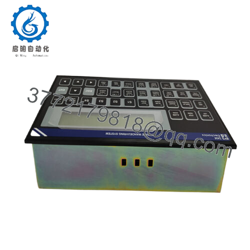
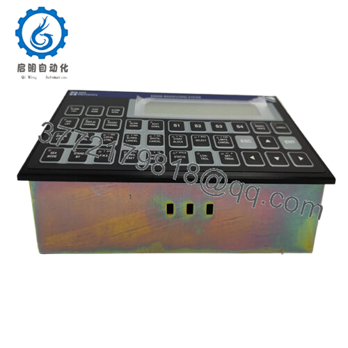
Product Model: EMP2200
Product Brand: SAM Electronics
Product Series / Category: Engine Monitoring / Control Module
Product Features:
- Continuous engine monitoring and alarm management in marine & power systems
- Robust design for harsh environments (marine grade)
- Multiple input / output channels for sensors & actuators
- Integration-ready with existing control and automation systems

- EMP2200
Applications & Industry Context
In marine, power generation, and heavy industrial environments, real-time monitoring and control of engines are critical for safety, reliability, and efficiency. The EMP2200 module from SAM Electronics fills that niche as a dedicated engine monitoring, protection, and control interface. Its role is especially vital on vessels where engine faults can cascade into major failures, or in power plants where uptime is nonnegotiable.
On ships, the EMP2200 is often part of the Engine Manoeuvring System (EMS) — it monitors key parameters (temperatures, pressures, speed, alarms) and ensures that both normal and emergency functions respond correctly. Indeed, one listing labels it precisely as “SAM Electronics EMP 2200-M Engine Manoeuvring System” with reference number 815.001.200.01. In such a role, the module interfaces with the main engine control system, generating warnings or executing shutdown commands when thresholds are crossed.
Beyond marine, the same module finds use in industrial engine set controls (generator sets, diesel engines in remote power installations). It acts as a bridge between sensor-level instrumentation and higher-level PLC / DCS / SCADA systems, performing local logic and safety oversight.
Integrators choose EMP2200 in retrofit scenarios too — when older engine control systems need modernization, this module can often be dropped into existing wiring looms, reducing redesign. Its rugged build supports deployment in vibration-prone, salt-laden, and humid environments.
Thus, the EMP2200 is not a mere peripheral — it is a mission-critical module that guards the heart of power and propulsion systems.
Technical Features & Benefits
Although public datasheets are limited, multiple sources hint at key capabilities of EMP2200, especially in its “-M” variant. Drawing from those, here are several plausible features and advantages:
- Engine Parameter Monitoring
The module monitors vital engine parameters: temperature, oil pressure, coolant pressure, speed (RPM), overspeed, fuel pressure, and more. It aggregates sensor data, compares to thresholds, and triggers alarms or protective actions when necessary. - Alarm & Protection Logic
Based on configured logic, it can initiate warnings (pre-alarm) or critical shutdowns (trip alarm). That logic is vital in preventing mechanical damage (e.g. overtemperature) or catastrophic failure. - Modular I/O Channels
The EMP2200 is advertised with multiple input and output channels. One listing describes “8 digital outputs and 4 analog outputs” for control tasks. Another listing notes “8 AI / 4 AO” modules in the EMP modules line. This modular I/O capability allows flexible mapping to actuators and sensor arrays. - Communication Interfaces
To integrate with control systems, EMP2200 supports industrial protocols such as Modbus RTU/TCP or Profibus DP. In marine settings, it may also interface to redundancy or navigation systems, passing data upstream. - Robust Environmental Design
Because it’s used in marine contexts, the EMP2200 is built to tolerate vibrations, humidity, salt spray, and temperature extremes. One supplier describes it as part of marine automation, reinforcing this expectation. - Hot-swap / Redundancy Capable
In advanced systems, multiple EMP modules may be installed, with one acting as backup. In engine control networks, redundancy is a common requirement, so the design likely supports fault detection and switchover. - Compact Integration
Compared to full PLCs or distributed controllers, the EMP2200 is relatively compact. This dimension allows mounting within engine control rooms or compact cabinets, minimizing footprint.
From a benefits perspective:
- Localized monitoring reduces data traffic on main control networks.
- Programmable logic in the module can enable quick response to anomalies, without waiting for central PLC logic cycles.
- Using a module specialized for engine oversight simplifies certification because it’s narrowly focused on critical tasks.
- Field engineers appreciate replacement flexibility and modular I/O mapping when integrating new sensor types.
Technical Specifications
Below is a compilation based on what sources offer and inferred capabilities. Because full official spec sheets aren’t public, treat these as an indicative baseline:
| Specification | Description / Value |
|---|---|
| Model / Variant | EMP2200 / EMP2200-M (Engine Manoeuvring) |
| Manufacturer | SAM Electronics |
| Category | Engine Monitoring & Control Module |
| I/O Capabilities | ~8 Digital Outputs, ~4 Analog Outputs; multiple digital/analog inputs |
| Communication Protocols | Modbus RTU / TCP, Profibus DP, possibly marine-specific interfaces |
| Operating Voltage | 24 VDC typical (industrial control) |
| Ambient Temperature Range | –20 °C to +70 °C |
| Protection / Certification | CE, RoHS, marine grade design (vibration / humidity) |
| Dimensions | ~ 25 cm × 15 cm × 5 cm (for module board) |
| Weight | ~1.2 kg |
| Mounting | Panel / DIN or rack mount (depending on variant) |
| Redundancy Support | Likely support for redundant modules / fault switchover |
| Certifications | Safety and marine compliance (e.g., marine EMC, shock / vibration) |
Because EMP2200 is used in marine engine systems, its design will likely satisfy marine regulatory requirements (vibration, salt spray, EMC) — though you should verify these with a full datasheet from SAM Electronics.
Product Role & System Fit
The EMP2200 module typically acts as a supervisory engine control and protection unit. In engine systems, it often sits between sensors (temperature, pressure, speed) and actuators (fuel valves, alarms, shutdown relays), and also interfaces upstream with PLC, control, or automation systems via industrial networks.
In a marine engine control architecture:
- Sensors feed analog/digital data to EMP2200.
- The EMP processes data, executes pre-defined logic, and triggers alarms or protective actions if thresholds are crossed.
- It sends status updates and process data to main control systems (PLC, DCS, bridge systems).
- In emergencies (overspeed, overpressure), the EMP issues command to shut down, interlock, or bring the engine to safe state.
Because its function is narrowly focused on engine safety and monitoring, the EMP2200 reduces the burden on the central control units. It can respond faster to critical thresholds, isolating engine risk from other system logic.
On the system integration side, the EMP2200 module often fits within marine automation, navigation systems, and redundant engine networks. In many shipboard setups, multiple EMP modules may be linked for symmetric engine control (e.g. twin-engine vessels), each module handling real-time monitoring locally but synchronized via network communication.
In power plant or generator control systems, the same role applies: it becomes a local fault-monitoring node dedicated to engine protection, with high reliability.
Installation & Maintenance Insights
Integrating the EMP2200 properly is vital to ensure reliability, safety, and performance. Below are best practices drawn from engineering experience with marine and industrial modules:
- Mounting & Orientation
Mount the module on a vibration-dampened panel or rack. Avoid mounting in direct line with engine vibration axes. Ensure sufficient airflow for thermal dissipation, especially if installed in closed cabinets. - Power & Grounding
Use stable, regulated 24 VDC supply with proper filtering. Provide solid ground references to sensor shields and module chassis to avoid noise injection. Use separate grounding for power and signal lines if possible. - Sensor Wiring & Shielding
Route sensor (thermocouple, RTD, pressure transmitters) wires away from high-current or power cables. Use shielded twisted pairs and terminate shields properly. Avoid running sensors parallel to noisy conductors. - I/O Mapping & Configuration
Before startup, define thresholds, hysteresis, alarms, and logic functions clearly. Use SAM Electronics’ configuration tools (if provided) to map sensors to I/O channels, set safe states, and define redundant behavior. - Commissioning in Steps
Bring the module online in phases: first power and basic diagnostics, then single-channel sensor checks, then full system integration with the engine control loop. Confirm that alarm limits and trips operate as expected under simulated fault conditions. - Maintenance Checks
Periodically inspect connectors for corrosion (especially in marine settings), perform functional tests of alarms and shutdown paths, and check calibration drift on analog sensors. Ensure module firmware is up to date and backup configurations are available. - Redundancy & Failover
If deployed in redundant systems, test switchover behavior regularly. Simulate module failure and confirm that backup takes over seamlessly without interrupting engine protection.
Following these steps reduces the chances of false trips, sensor noise issues, or module failure — especially in mission-critical installations.


