 WhatsApp: +86 16626708626
 Email:
  Phone: +86 16626708626
Description
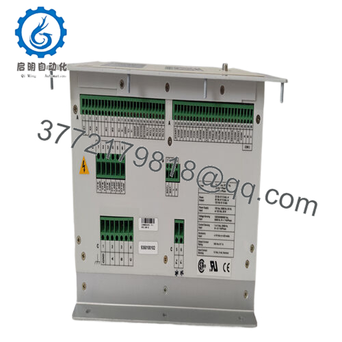
Product Model: DECS-200-2C
Product Brand: Basler Electric
Product Series / Family: DECS (Digital Excitation Control System)
Product Features:
- Supports multiple DC field voltage levels: 32 V, 63 V, 125 V (up to 15 A continuous)
- Microprocessor-based control with PWM output stage for improved performance under non-linear load conditions
- Built-in modes: AVR (Automatic Voltage Regulation), Var / PF control, field current regulation, mode tracking between active/inactive modes
- Communications: front RS-232, side RS-232 (for autotracking), RS-485 (Modbus) for remote communications

- DECS-200-2C
Applications & Industry Context
In power generation and synchronous machine systems, precise control of the excitation (field current) is central to regulating output voltage, reactive power (vars), and power factor. The DECS-200-2C is designed as a digital excitation controller, replacing older analog field regulators and giving more flexibility, diagnostics, and control functionality.
You’ll commonly find DECS-200-2C in generator sets, utility plants, backup / standby power systems, renewable hybrid systems, or wherever a synchronous machine’s excitation must be managed digitally. Its flexibility in field voltage and current makes it suitable across a wide range of machines (small to medium size).
In modernization or refurbishment projects, digitizing the field control stage with a module like DECS-200-2C retains existing generator hardware while upgrading control precision, protection, and connectivity.
Because Basler is a known name in excitation control, many plants already have experience or spare inventory—making the DECS-200-2C a practical choice when replacements or upgrades are needed.
Technical Features & Benefits
Here’s a deeper dive into what DECS-200-2C provides and how it benefits system performance:
Multi-Voltage Field Output Support
This controller supports field voltage outputs of 32 V, 63 V, or 125 V DC, while delivering up to 15 A continuous DC current. This flexibility allows use across machines with differing field voltage requirements without needing different model variants.
PWM Power Stage for Improved Performance
Using a pulse-width modulated (PWM) output stage, DECS-200-2C maintains better performance under non-linear loads, reducing ripple, improving steady regulation, and providing faster dynamic response compared to older linear regulators.
Control Modes & Tracking
It supports several control modes:
- Automatic Voltage Regulation (AVR) as the primary operating mode
- Var / Power Factor Control, enabling the system to manage reactive power
- Field Current Regulation (FCR / manual mode) for scenarios requiring direct current control
- Mode Tracking & Autotrack: Inactive modes automatically follow the active one; external autotracking between DECS units is also supported
This flexibility ensures that control strategy can adapt to system demands without switching hardware.
Protection & Limiting Functions
To safeguard machine and controller, the DECS-200-2C includes protection features:
- Overvoltage / undervoltage of field circuits
- Field overcurrent protection
- Minimum excitation limiting
- Underexcitation, overexcitation limiters
- Stator current limiting
- Exciter diode monitoring (EDM)
- Watchdog / failure detection functions
- Eight generator protection features (e.g. loss of field)
Such comprehensive protection ensures reliability and avoids damage under fault conditions.
Communication & Configuration
It provides multiple communication ports:
- COM0 (front RS-232) for local PC access, configuration, diagnostics
- COM1 (side RS-232) for linking primary and backup DECS units for autotrack
- COM2 (RS-485) supporting Modbus protocol for integration with remote systems up to ~4000 ft away
You can configure it locally via front panel or remotely via PC software. The system also provides data logging (sequence of events, oscillography) and metering of generator parameters.
Technical Specifications
| Specification | Description / Value |
|---|---|
| Model / Part | DECS-200-2C (Digital Excitation Control System) |
| Field Voltage Output Options | 32 Vdc, 63 Vdc, 125 Vdc |
| Continuous Field Current | 15 A dc |
| 10-Second Forcing / Overload Capability | Up to 2× current / voltage for 10 seconds (varies by output level) |
| Regulation Accuracy (Voltage mode) | ±0.25% (AVR mode) |
| Control Modes | AVR, Var / PF, FCR (manual) |
| Sensing | True RMS sensing, single-phase or three-phase voltage sensing; current sensing 1 A / 5 A ranges |
| Communications Ports | COM0 (RS-232 front), COM1 (RS-232 side), COM2 (RS-485 Modbus) |
| Power / Control Supply | 16-60 Vdc (30 W), 85-132 Vac (50 VA), 90-150 Vdc (30 W) |
| Operating Temperature | –40 °C to +60 °C |
| Protection / Limiting Features | Overvoltage, undervoltage, field current limiters, stator current limiting, EDM, watchdog, mode tracking |
| Metering & Logging | <1% metering accuracy for ~12 generator parameters; sequence of events recording; oscillography (8 records) |
| Communication Range | RS-485 line (~4000 ft) |
| Certifications / Standards | CE, UL recognition; complies with IEEE C37.90.1 (surge and transient immunity) |
| Discontinuation / Status | Listed as “Discontinued by Manufacturer” by some distributors |
Installation & Maintenance Insights
When deploying DECS-200-2C, consider these field practices and guidelines:
- Mounting & Clearance
Mount the controller in a vibration-resilient enclosure with good ventilation. Leave clearance for wiring, heat dissipation, and access to the front panel. - Power and Sensing Wiring
- Use properly rated cables for field voltage outputs (DC) to exciter field windings.
- Use shielded wiring for voltage & current sensing circuits; route away from noisy power lines.
- Voltage sensing may be single-phase or three-phase; ensure correct configuration.
- Grounding & Reference
Proper grounding of common reference, shunts, and shielding are essential to avoid measurement errors or noise coupling. - Configuration & Parametrization
- Configure field voltage/current limits, compensation settings, exciter matching, and droop or PF modes as required.
- Enable tracking or synchronizing between redundant controllers if used.
- Use the front panel interface or PC software for initial setup and validation.
- Communication Integration
Use the RS-232 port for local diagnostics; configure the Modbus settings on RS-485 port and verify communications with SCADA / PLC systems. - Protection Verification
During commissioning, test the built-in protection functions: field overcurrent, undervoltage, exciters diode failure, etc. Observe how the controller responds to abnormal conditions. - Periodic Maintenance & Calibration
Check terminal connections for tightness and corrosion. Verify voltage and current measurement accuracy periodically. Confirm that firmware and settings remain stable over time. - Spare / Replacement Strategy
Because the DECS-200-2C is listed as discontinued by some distributors (Radwell) , stock a spare unit of the same variant and maintain configuration backups to allow rapid swap-out.