 WhatsApp: +86 16626708626
 Email:
  Phone: +86 16626708626
Description
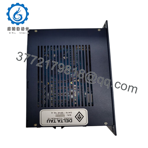
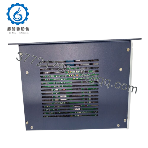
Product Model: CLIPPERT3
Product Brand: Delta Tau (Turbo PMAC / Clipper family)
Product Series: Clipper / Turbo PMAC
Product Features:
- Multi-axis motion controller (minimum 4 servo or stepper axes)
- 80 MHz DSP56303 CPU with high-speed interface and I/O
- 32 general-purpose digital I/O, encoder inputs, analog outputs
- Ethernet, RS-232, optional expansions for added axes and peripherals

- CLIPPERT3
Applications & Industry Context
In environments where precise motion control, synchronization, and real-time processing matter — such as robotics, semiconductor manufacturing, or precision milling — the CLIPPERT3 finds its niche. Rather than acting as a general-purpose PLC, this module is specifically engineered for motion systems, coordinating multiple servo axes, reading feedback encoders, and outputting control signals with millisecond or microsecond accuracy.
Many machine OEMs integrate Clipper-based controllers inside their motion cabinets to handle tasks like multi-axis coordination, synchronized interpolation, gear compensation, and vibration damping. The CLIPPERT3 often pairs with amplifier racks, I/O modules, and expansion boards in tight spaces. Thanks to its dual communication links (Ethernet, RS-232) and compact board footprint, it works well embedded within complex assemblies.
One common real-world scenario: pairing multiple CLIPPERT3 units to control gantries, robotic arms, or linear motor stages. Engineers appreciate how Clipper controllers handle coordinated moves, backlash compensation, and cam profiling in real time. In semiconductor wafer steppers, for example, this module might manage stage movement while a higher-level system handles recipe logic or scanning.
Other industries — printing, packaging, scanning, motion simulation rigs — also benefit from deterministic motion control. In each, the CLIPPERT3 takes on the role of the “real-time stage controller” while the supervisory system remains focused on process logic.
Product Role & System Fit
The CLIPPERT3 acts primarily as a dedicated motion processor within the Turbo PMAC / Clipper family. Its job is to execute motion algorithms — PID control, feedforward, notch filtering, trajectory planning — and interface with feedback devices and amplifiers.
It is not meant to replace PLC logic or general control but rather complements them. In a typical system, the CLIPPERT3 handles servo loops and position demands; a PLC or automation controller issues setpoints, handles non-motion I/O, and coordinates process logic. The Clipper passes status feedback and alarms back to the supervisory system via Ethernet or serial interface.
Its compatibility with accessory boards means you can scale beyond the base 4-axis — stacking or expanding to 8 axes, more analog or digital I/O, or specialty outputs — all while preserving synchronization across the system. This modular scalability ensures the CLIPPERT3 fits in varied system sizes without forcing operators to oversize controller hardware.
Because it’s part of the Delta Tau Turbo PMAC / Clipper ecosystem, firmware, command sets, and utilities are shared with other Clipper and PMAC modules. That reduces learning curves for integrators and leverages a mature toolchain already in industry use.
Technical Features & Benefits
The CLIPPERT3 offers a compelling mix of hardware capabilities and functional motion control features:
- Processor core & memory: It uses an 80 MHz DSP56303 core, typical of the Clipper line, with 256k × 24-bit user SRAM and 1M × 8 flash memory for firmware and backups.
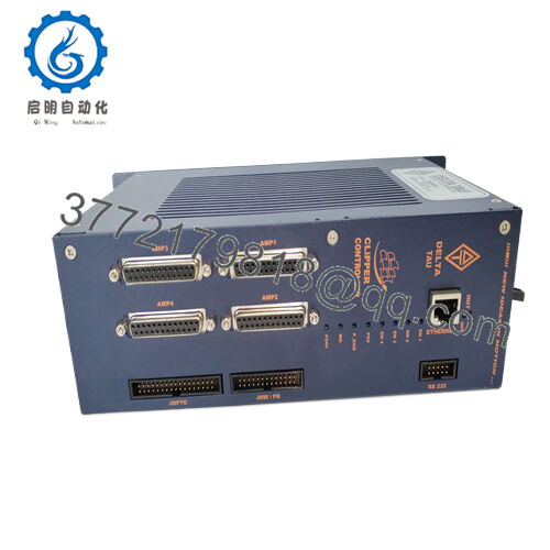
- I/O and axis interface: The base version supports 4 servo/stepper channels, each with analog 12-bit +10 V outputs, pulse-&-direction digital outputs, differential or single-ended encoder inputs, and Hall sensor inputs.
- General-purpose digital I/O: 32 TTL-level I/O points (multiplexer-compatible, “Opto-22” style) selectable by byte for direction.
- Communications: Ethernet (100 Mbps), RS-232 interface, and USB 2.0 support for configuration or data transfer.
- Optional expansions: Additional A/D channels, D/A converters, or more axes via accessory boards like ACC-1P or ACC-8FS.
- Diagnostics and feedback: Built-in diagnostics for I/O errors, encoding anomalies, and interface health, which helps during commissioning and maintenance.
- Operating conditions: The Clipper module is rated for industrial temperature ranges, and mounting requires airflow, grounding, and attention to noise shielding.
These features translate to tangible benefits: excellent interpolation performance, predictable response times, flexible expansion, and deep diagnostics — critical in motion-centric automation systems.
Technical Specifications
| Specification | Description |
|---|---|
| Model | CLIPPERT3 (Turbo Clipper T3) |
| Processor | DSP56303, 80 MHz |
| Memory | 256k × 24-bit SRAM, 1M × 8 flash |
| Axes (base) | 4 servo/stepper channels |
| Analog Outputs | 12-bit, ±10 V per axis |
| Encoder Inputs | 3-channel differential/single-ended per axis |
| Digital I/O | 32 TTL-level I/O points |
| Communications | Ethernet 100 Mbps, RS-232, USB 2.0 |
| Optional Expandability | ADC, DAC, more axes via accessories |
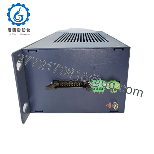
| Power Supply | 5 V logic, ±12 V DAC (via 4-pin terminal) |
| Operating Temperature | Industrial spec (–20 °C to +60 °C or better) |
| Mounting | PCB mounting or chassis with standoffs; requires airflow and grounding |
| Dimensions | Approx 110 × 220 mm board format (4.25″ × 8.5″) |
| Certifications | Industrial hardware design — conforms to Delta Tau industrial standards |
Installation & Maintenance Insights
Installing a CLIPPERT3 requires attention to layout, grounding, thermal management, and signal integrity — factors that in practice make the difference between smooth operation and noise or stability issues.
Begin by mounting the board on a smooth, conductive backpanel or chassis, using standoffs. Be sure to break through any anodization with lock washers in multiple mounting points to ensure a low-impedance path to chassis. Maintain clearance above and below the board (≈ 0.4 inches / 10 mm) for airflow.
Power wiring must supply 5 V logic and ±12 V for DAC channels (if in use). Use twisted-pair or shielded wiring for analog lines. Grounds should meet reference, and wiring should avoid long loops near high-current conductors. The manual warns: “install in enclosure that prevents excessive ambient temperature” and ensure ground network symmetry.
For signal wiring: encoder and I/O headers are 50-pin or 34-pin IDC headers; ensure correct pin mapping and shielding. I/O diagnostics will help catch wiring faults—verify continuity before applying power.
During commissioning, monitor internal diagnostics, test each axis motion in isolation, validate encoder feedback, and check analog output linearity. Subtle configuration errors often show only under load or dynamic motion; so plan thorough functional testing under real system conditions.
For maintenance: keep firmware and configuration backups; record any error logs or device hits. Periodically inspect connectors, re-seat modules, and ensure ventilation openings are clear (dust can degrade thermal performance). If temperature or humidity extremes occur, consider active forced-air cooling.
Because the CLIPPERT3 is often integrated deep within machinery, hot-swap is rarely practical; plan for module replacements during scheduled downtime and keep a spare board in inventory.