BENTLY 3500/54 133396-01 Electronic Overspeed Detection System
BENTLY 3500/54 133396-01 Electronic Overspeed Detection System
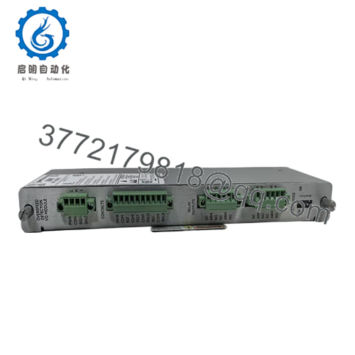
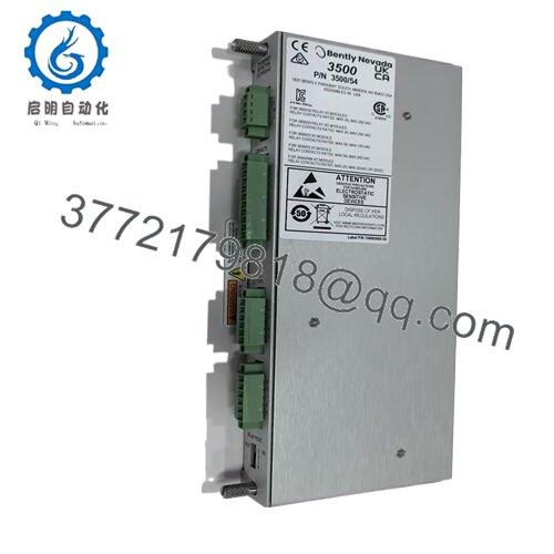
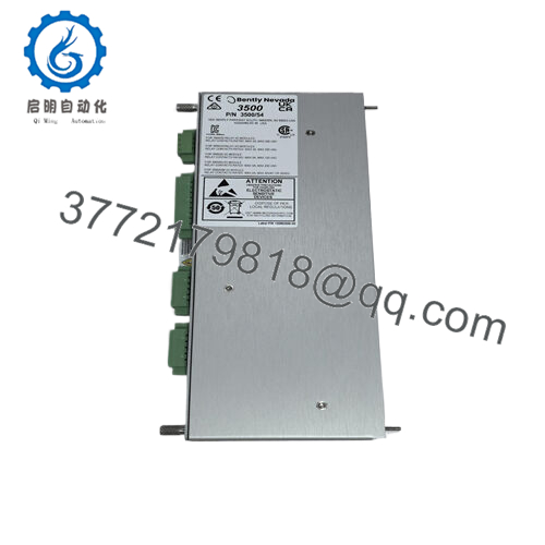
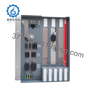
The BENTLY 3500/54133396-01 is a key component within the 3500 series machinery detection system. Each overspeed detection module accepts a single transducer signal from a proximity probe transducer or magnetic pickup. The input signal range is +10.0 V to – 24.0 V, and signals exceeding this range are limited internally by the module.
Model Number3500/54133396-01
BrandBENTLY Nevada
TypeElectronic Overspeed Detection System
Input VoltageInput signal range: +10.0 V to – 24.0 V
Operating Temp Range- 30 °C to +65 °C
Mounting StyleInstalled in 3500 rack
Weight0.45 kg
Interface/BusCommunicates within 3500 system backplane
ComplianceMeets API 670 and 612 standards for overspeed protection
Typical Power Draw8.0 watts
TransducersAccepts signals from BENTLY Nevada 3300 8 mm proximitor ®, 3300 16 mm htps, 7200 5 mm, 8 mm, 11 mm, and 14 mm proximitor ®, 3300 ram proximitor ®, or magnetic pickups
The BENTLY 3500/54133396-01 is a key component within the 3500 series machinery detection system. Each overspeed detection module accepts a single transducer signal from a proximity probe transducer or magnetic pickup. The input signal range is +10.0 V to – 24.0 V, and signals exceeding this range are limited internally by the module.
350054 133396-01
It functions as part of a redundant tachometer system. Multiple 3500/54 modules can be combined to form a 2 – out – of – 2 or 2 – out – of – 3 (recommended) voting system. In a 2 – out – of – 3 voting system, for example, at least two out of the three modules must detect an overspeed condition for an alarm to be triggered and protective actions to be taken. This redundancy significantly enhances the reliability of the overspeed detection system, reducing the chances of false alarms or missed detections.
The module is integrated into the 3500 rack, which requires redundant power supplies for added stability. It communicates with other modules in the rack, such as the main processor module and various I/O modules. When an overspeed condition is detected, it can send signals to other components in the system to initiate corrective actions, such as shutting down the equipment or reducing the power input.
350054 133396-01
Technical specifications:
Model Number3500/54133396-01
BrandBENTLY Nevada
TypeElectronic Overspeed Detection System
Input VoltageInput signal range: +10.0 V to – 24.0 V
Operating Temp Range- 30 °C to +65 °C
Mounting StyleInstalled in 3500 rack
Weight0.45 kg
Interface/BusCommunicates within 3500 system backplane
ComplianceMeets API 670 and 612 standards for overspeed protection
Typical Power Draw8.0 watts
TransducersAccepts signals from BENTLY Nevada 3300 8 mm proximitor ®, 3300 16 mm htps, 7200 5 mm, 8 mm, 11 mm, and 14 mm proximitor ®, 3300 ram proximitor ®, or magnetic pickups
Contact Us Phone:+86 16626708626 WeChat/WhatsApp:+86 16626708626 Email: 3772179818@qq.com
350054 133396-01
Main features and advantages:
Engineered for industrial – grade reliability, the BENTLY3500/54133396-01 offers long – term performance in harsh operating environments. Its ability to quickly detect overspeed conditions and initiate protective actions helps prevent costly equipment repairs and unplanned downtime.
The redundant design and compliance with industry standards give plant operators and engineers peace of mind. In power plants, for example, where turbines operate at high speeds and under high stress, the overspeed detection system can act as a crucial safety net. In refineries, where compressors are used to move gases and liquids, the 3500/54 can prevent potentially dangerous situations caused by overspeed.
By accurately detecting overspeed events, it also helps in optimizing the maintenance schedule of the equipment. Instead of relying on reactive maintenance after a failure, the system enables proactive maintenance, reducing the overall cost of equipment ownership.
350054 133396-01
Application areas:
Power plants are one of the primary users of the BENTLY 3500/54133396-01. Steam turbines, gas turbines, and generators in power plants operate at high rotational speeds. Any sudden increase in speed can lead to severe damage. The overspeed detection system continuously monitors the shaft speed and can quickly shut down the turbine if an overspeed condition is detected, protecting the expensive equipment and ensuring the stability of the power grid.
In the oil and gas industry, compressors used for gas transportation and processing are also equipped with the 3500/54 system. These compressors often operate in remote locations, and an overspeed event could lead to significant production losses and safety hazards. The system’s reliable performance in harsh environments, such as offshore platforms with salt – laden air and extreme temperatures, makes it an ideal choice for these applications.
Manufacturing plants that use large – scale motors for various production processes also benefit from the BENTLY 3500/54 overspeed detection system. In situations where a motor’s speed control system malfunctions, the overspeed detection system can prevent damage to the motor and associated machinery, ensuring continuous production.
350054 133396-01
Related products:
3500/53 Modules: Can be used in combination with the 3500/54 to form different voting configurations for enhanced reliability. They work in tandem to provide a more comprehensive overspeed detection solution.
Other Overspeed Detection Systems from Different Manufacturers: Some other companies may offer overspeed detection products, but they may not have the same level of integration with the BENTLY 3500 series monitoring system. The BENTLY 3500/54 has the advantage of seamless integration within the 3500 ecosystem, ensuring compatibility with other modules and ease of use for existing 3500 system users.
Installation and maintenance:
Before installing the BENTLY3500/54133396-01, verify that the 3500 rack has redundant power supplies installed—this is critical for maintaining overspeed protection even during power fluctuations. Check that the transducer cables are properly shielded to prevent electromagnetic interference, which can distort speed signals. Ensure there’s adequate space around the module in the rack for cooling, as prolonged exposure to high temperatures can affect performance. It’s also important to confirm that the module’s firmware is compatible with the rack’s main processor to avoid communication issues.
For ongoing maintenance, regularly inspect the transducer connections to ensure they’re tight and free from corrosion—loose connections can cause false speed readings. Check the module’s LED indicators weekly: a steady green light indicates normal operation, while a flashing red light signals an overspeed event or system fault. Perform a yearly functional test by simulating an overspeed condition to verify that the module triggers the appropriate alarms and protective actions. This test should be conducted during scheduled downtime to avoid disrupting operations.

 WhatsApp: +86 16626708626
 Email: 3772179818@qq.com
 Phone: +86 16626708626