 WhatsApp: +86 16626708626
 Email:
  Phone: +86 16626708626
Description
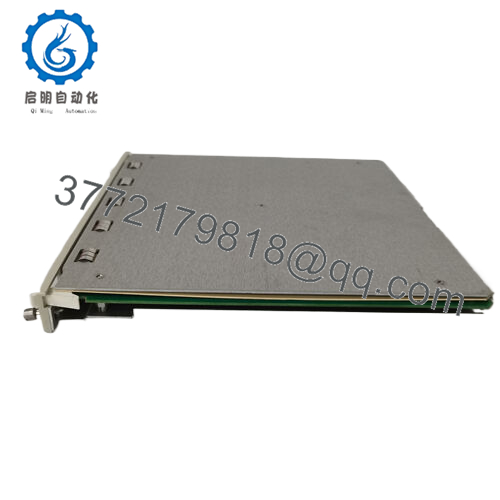
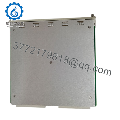
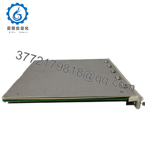
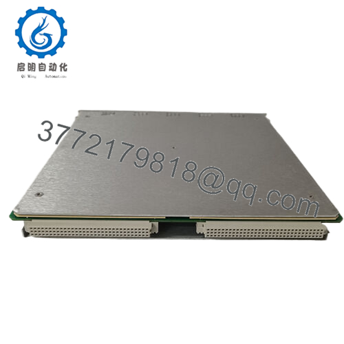
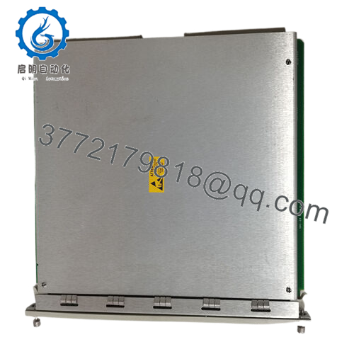
Product Model: Bently 3500/33 149986-01
Brand / Series: Bently Nevada / 3500 Condition Monitoring
Module Type: 16-Channel Relay Output Module, full-height
Key Features:
- Provides 16 independent relay outputs for alarm, control, or logic functions in a 3500 rack environment.
- Programmable Alarm Drive Logic per channel (AND / OR logic) using input statuses (Alert / Danger / Not OK) or measured variables.
- Full-height format; supports I/O module behind it for backplane or wiring interface.
- Power consumption ~5.8 watts (typical) and compact physical footprint (241 mm height × 24.4 mm width × 242 mm depth).
- 350033 149986-01

- 350033 149986-01
Applications & System Context
In a Bently 3500 machinery protection rack, apart from sensors, monitors, and communication modules, you often need to dispatch alarms, drive external hardware (e.g. shutdown valves, horns, annunciators), or implement logic decisions based on measured variables. The 3500/33 relay module is used exactly for that. The 149986-01 variant is one of the ordering codes for the 16-channel output version.
In practice, in a gas turbine or compressor installation, you might map over-temperature, excessive vibration, or speed deviation alarms into discrete relay outputs which interface to safety systems, DCS, or emergency trips. The 3500/33 module, with its multiple outputs and programmable logic, is often placed to the right of the TDI (Transient Data Interface) in the rack to serve as the relay stage.
Thanks to its flexibility in logic and voting, 149986-01 can be used in redundant architectures or to centralize relay logic for multiple channels. It reduces the need for external relays or logic cabinets, simplifying the system architecture.
Because the 3500/33 module is internally integrated in the rack, its relay outputs are closely tied to the monitor modules and configuration software — allowing synchronized alarm generation or logic changes from the same platform.
Role & System Integration
Within the 3500 system, 149986-01 behaves as a relay output module. Let’s break down how it fits:
- It occupies a full-height front slot in the rack (to the right of the TDI or other modules) and is matched with a rear I/O module (for wiring) behind it.
- The main 3500/33 logic module handles the relay control logic and communicates with backplane interfaces; the rear I/O module manages the wiring to external devices like solenoids, contactors, or annunciators.
- Each of the 16 output relays is programmable using the 3500 Rack Configuration software. You define which inputs (Alert, Danger, Not-OK, or measured variables) feed into each relay’s Alarm Drive Logic, selecting AND, OR, voting, latching options.
- The module also supports channel alarm LEDs, OK LED, TX/RX LED for communications diagnostics, and status monitoring of module health.
- Because it is part of the 3500 modular backbone, its wiring and logic mapping are controlled centrally via the same rack configuration tools, giving tight consistency and maintainability.
One nuance to note: in Triple Modular Redundant (TMR) systems, one should use the dedicated TMR relay modules (e.g. 3500/34) instead of standard 33 modules.
Essentially, 149986-01 is the bridge between internal condition monitoring logic and external control or alarm hardware — a critical piece of the “last mile” in protection systems.
Technical Features & Benefits
Let’s lay out the distinguishing features of 149986-01 and how they benefit real-world systems:
16 Independent Relay Outputs
You get 16 relays in one module — a high capacity for alarm and control mapping. Fewer modules can cover more functions.
Programmable Alarm Drive Logic per Relay
Rather than fixed logic, each relay’s logic can be configured (via AND, OR, combinations) using multiple sources (Alert / Danger status, Not-OK, or measured variables). This flexibility saves external logic hardware.
Voting Logic & Latching Options
The 3500/33 module supports voting logic (e.g. majority voting, redundant signal paths) and relay latching per channel. This supports safety or conservative logic strategies when needed.
Compact & Integrated Design
Although full-height, the module maintains standard 3500 mechanical dimensions and integrates seamlessly with backplane and I/O wiring.
LED & Diagnostic Feedback
Front-panel LEDs convey module and channel health: OK, TX/RX, Channel Alarm. This helps with commissioning and troubleshooting.
Low Power Consumption
Typical power draw is ~5.8 W, modest for a 16-output relay board. This reduces thermal stress in dense racks.
Wide Environmental Tolerance
Designed for industrial ambient conditions (–40 °C to +85 °C storage, etc. as typical relay modules).
Redundancy & Scalability
You can stack multiple 3500/33 modules in a rack to scale outputs. Logic mapping across modules is unified.
Because of these features, 149986-01 gives integrators a powerful, centralized relay output solution in the 3500 ecosystem.
Technical Specifications Table
Below is a specs table derived from the 3500/33 datasheet and supplementary vendor data:
| Parameter | Specification / Detail |
|---|---|
| Product / Model | Bently 3500/33 149986-01 (16-Channel Relay Output Module) |
| Module Type | Full-height front relay logic module (paired with rear I/O module) |
| Relay Outputs | 16 independent relays, programmable per channel |
| Relay Logic | Alarm Drive Logic (configurable AND / OR combinations) using Alert, Danger, Not-OK, or measured variables |
| Power Consumption | ~5.8 W typical |
| Module Dimensions (front) | 241 mm × 24.4 mm × 242 mm (height × width × depth) |
| Module Weight | ~0.7 kg (1.6 lb) |
| Rear I/O Module | Dimensions 241 mm × 24.4 mm × 99.1 mm, weight ~0.4 kg (for wiring interface) |
| Environmental / Storage | Storage –40 °C to +85 °C (as typical for relay modules) |
| LED Indicators | OK, TX/RX, Channel Alarm per output channel |
| Relay Contact Types | Standard relay contacts compatible with typical industrial loads (voltage and current depend on system wiring) |
| Logic / Voting Modes | Support for voting, latching, AND/OR combination logic per channel |
| Redundancy Use | In TMR applications, a TMR relay module (3500/34) is recommended instead of standard 33 modules |
Installation & Maintenance Insights
From field experience with 3500 relay modules and insights from Bently literature, here are tips and caveats for 149986-01:
Slot & Orientation
Insert 149986-01 into a full-height front slot to the right of the TDI (or adjacent to other modules). Behind it, the rear I/O module must be installed in the matching rear slot for wiring interface. Mis-alignment will break relay wiring.
Wiring Practices
Use shielded wires where long cable runs exist. Separate power wiring from sensitive signal wires to avoid cross-talk or induced interference on relay lines.
Logic Mapping & Configuration
Carefully define relay logic in the 3500 Rack Configuration software. Because each relay can draw from multiple input sources, avoid logic conflicts, overlapping conditions, or circular logic routes.
Load Testing
Before final commissioning, test relay outputs under the expected loads (voltage, current) and observe switching responses. Confirm that the contacts perform reliably across temperature and run-in.
Monitoring LEDs & Diagnostics
Check the OK and TX/RX LEDs to confirm module health and communications. Use Channel Alarm LEDs to verify which relays are active or in fault state. These indicators are crucial during commissioning or troubleshooting.
Thermal Management
Although a relay module is not high-power, the density of modules in racks may cause localized heating. Ensure adequate ventilation. Avoid adjacent high-heat modules that might influence contact reliability.
Periodic Inspection
Over time, relay contacts, wiring terminals, or solder joints may loosen or degrade. Regularly inspect contacts, tighten connections, and test relay responses as part of preventive maintenance.
Replacement Strategy & Spares
Maintain a spare 149986-01 (same revision) module pre-configured where possible. Because relay logic may be unique to your installation, duplicate configuration files and logic settings to accelerate replacement.
Firmware / Compatibility Checks
If Bently issues firmware updates for the 3500/33 module line, ensure 149986-01 is compatible. Back up existing logic configurations before updating.
Using in Redundant / TMR Systems
In systems requiring fault-tolerant relay behavior, standard 3500/33 modules like 149986-01 may not be sufficient—use the dedicated 3500/34 TMR Relay Module for triple-redundant architectures. 快速时间在线