 WhatsApp: +86 16626708626
 Email:
  Phone: +86 16626708626
Description
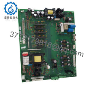
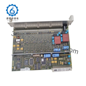
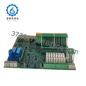
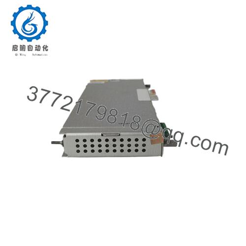
Product Model: Bently 146031-01
Brand: Bently Nevada / GE
Series / System: 3500 / 3500/22M Transient Data Interface (TDI)
Key Features:
- Acts as an I/O / Interface module (TDI) for the 3500 monitoring rack, combining rack interface and communications processor capabilities.
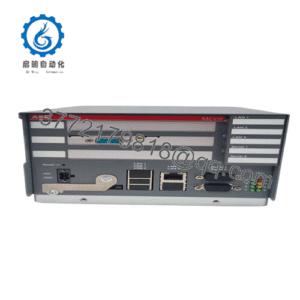
- Supports 10Base-T / 100Base-TX Ethernet connectivity for data transmission to host systems (System 1 etc.).
- Always occupies Slot 1 in the 3500 rack (next to power supplies) as the rack’s front-end interface.
- Static (steady-state) data capture is standard; dynamic / transient capture is enabled via an optional Channel Enabling Disk
Applications & System Context
Within the Bently 3500 machinery protection and vibration monitoring family, the 146031-01 module plays a central role in bridging the internal rack modules to external host systems. The 3500 racks are populated with “M” series monitor modules (e.g. 3500/40M, 3500/42M) that measure vibration, proximity, temperature, and other signals. The TDI (Transient Data Interface) is the module that communicates those measured values (both steady-state and transient waveform data) out to supervisory software (such as GE / Bently’s System 1) over Ethernet.
In practice, the 146031-01 is employed in rotating machinery applications where diagnostics, waveform capture, trending, and condition monitoring are required. For example, a turbine or compressor skid might host a 3500 rack; the 146031-01 ensures that data from monitoring modules is delivered to the control room, historian, or analytics system. Because it merges the functions of the older Rack Interface Module (RIM) and communications processor, it simplifies system architecture and reduces extra boards.
Retrofitting older 3500 systems that used a standalone RIM + communications bridge is a common use case: replacing those with a 146031-01 consolidates functionality and streamlines wiring. Because static data capture is built in, the module is essential even if transient capture is not used; installing the optional Channel Enabling Disk adds transient capability.

- 146031-01
- 146031-01
Another context is in redundant or triple-modular-redundant (TMR) monitoring systems: because the 146031-01 is not part of the critical protection path, its failure does not block trip logic, giving flexibility in maintenance or replacement
Role, Integration & Architecture
Within the 3500 rack, the 146031-01 occupies Slot 1, immediately adjacent to the power supplies, as required by system design.
Its primary functions:
- Rack interface / internal communication
It performs what the older Rack Interface Module (RIM) used to: control bus access, data multiplexing, addressing, and coordination with the monitor modules in the same rack. The 146031-01 handles steady-state data polling, health/status information, and communication to M-series modules. - Communications / Ethernet outbound
It acts as the communications processor: collecting the data (static and, when enabled, transient waveform capture), packaging it over Ethernet to the host or diagnostic software. Because of this, the module supports 10Base-T / 100Base-TX Ethernet connectivity. - Transient / waveform capture support
In many installations, the base 146031-01 captures only static (steady-state) data. To perform high-resolution waveform capture or transient event logging, a Channel Enabling Disk must be installed. When present and configured, the module collects waveform data from the M-modules and forwards them.
Importantly, while it handles data and communications, the 146031-01 is not part of the critical trip/protection logic path. That means a failure in the module affects data reporting or diagnostics, but not the core protection functions of the 3500 rack.
From a system integrator’s perspective, replacing a combined RIM + communications bridge with the 146031-01 reduces module count, simplifies configuration, and tightens the internal system design.
Technical Features & Benefits
Here are key capabilities and advantages of 146031-01, based on datasheet and vendor sources:
Ethernet Connectivity: 10/100 Mbps
The module supports 10Base-T / 100Base-TX Ethernet interface (auto-sensing) as its communications path to host systems.
Power Consumption & Input Ratings
Typical power consumption is modest (≈ 10.5 Watts).
Input / output specifications include an OK relay contact (for Rack health) rated 5 A @ 24 Vdc / 120 Vac, with optional gold-plated contacts capable of low-current switching (as low as 1 mA @ 1 Vdc).
LED / Status Indicators
The datasheet indicates front-panel LED indicators, including OK LED, TX/RX LED (network activity), TM LED (Trip Multiply mode), and CONFIG OK LED to show valid rack configuration.
Arc Protection / Relay Contact Protection
The module includes arc suppressors for the OK relay contacts to reduce wear and protect against transient voltage spikes.
Operating Conditions / Thermal / Humidity
While exact ranges vary by listing, published sources indicate operates from –30 °C to +65 °C, with storage temperature to –40 °C / +85 °C.
Mechanical & Physical Traits
Dimensionally, multiple vendor listings show weights in the ~0.8 kg range.
In some listings, footprint is given as 13.0 cm × 1.9 cm × 19.1 cm (though check for exact variant) in module assembly configurations.
Upgraded / Replacement Pairing
Some sources note that the 146031-01 is used in conjunction with TDI modules like part 288055-01 in system assemblies (3500/22M + TDI).
Legacy / Lifecycle Status
Given the age of the 3500 series, 146031-01 modules are often stocked in surplus / refurbished inventory. While no universal End-of-Life notice is shown in the immediate sources collected, the reliance on third-party vendors and surplus markets suggests limited new production.
Technical Specifications Table
Below is a unified table summarizing specifications of Bently 146031-01, compiled from datasheet snippets and vendor listings:
| Parameter | Specification / Detail |
|---|---|
| Model / Part Number | Bently Nevada 146031-01 |
| Module Type / Role | Transient Data Interface (TDI) I/O Interface / Rack Interface |
| System | Bently 3500 monitoring family (3500/22M) |
| Ethernet Interface | 10Base-T / 100Base-TX, auto-sensing |
| Power Consumption | ~10.5 Watts |
| OK Relay Rating | 5 A @ 24 Vdc / 120 Vac (standard); gold-plated contacts support lower currents down to ~1 mA @ 1 Vdc |
| LED / Indicators | OK, TX/RX, TM, CONFIG OK status LEDs |
| Operating Temp | –30 °C to +65 °C (vendor listing) |
| Storage Temp | –40 °C to +85 °C |
| Relay Protection | Arc suppressors built in for OK relay |
| Location in Rack | Slot 1 in 3500 rack (adjacent to power supplies) |
| Transient Capture | Optional via Channel Enabling Disk |
| Network / Assembly Pairing | Often used with TDI / Ethernet modules like 288055-01 in 3500/22M assemblies |
| Weight | ~0.8 kg (vendor listings) |
| Dimensions | ~13.0 cm × 1.9 cm × 19.1 cm in some assembly contexts |
Installation, Commissioning & Maintenance Insights
From experience with Bently / 3500 systems and typical best practices, here are actionable guidance when working with 146031-01.
Slot & Backplane Placement
Always install the 146031-01 in Slot 1 (RIM slot)—directly adjacent to the rack’s power supplies. Mis-placement will break communications and may cause errors.
Confirm full insertion and engagement with the backplane connector. A poor connection could lead to data issues or module malfunction.
Firmware & Compatibility
Ensure that the module’s firmware is compatible with the M-series monitor modules and the host software (System 1 or equivalent). When upgrading or replacing older RIMs, confirm register mapping and communication addressing.
If enabling transient waveform capture (via Channel Enabling Disk), ensure proper configuration of channels, capture parameters, and host software support.
Networking Setup
Because data travels over Ethernet, ensure the link parameters (speed, duplex, VLAN, addressing) are correctly configured. Latent or dropped packets may degrade data integrity. Use industrial-grade Ethernet cabling and switches.
Health Indication / LED Monitoring
During commissioning, confirm LED status (OK, TX/RX, TM, CONFIG OK) on the module correspond to expected operational states. Use these as a diagnostic aid for communication and configuration status.
Relay / Contact Testing
Test the OK relay contacts under expected loads (e.g. 5 A at rated voltages) and confirm arc suppression functionality. Verify contact closure/opening under a range of voltage conditions.
Temperature and Ventilation
In enclosed racks, monitor the module’s temperature under load. Ensure proper airflow and avoid placing high-heat modules adjacent without spacing. Temperature stress can affect longevity.
Periodic Checks & Diagnostics
Regularly check configuration validity, communication performance, network statistics, and error logs. For critical systems, simulate data traffic and waveform capture during maintenance windows as a validation.
Spare Module Strategy
Given the age of 3500 systems, maintain a spare 146031-01 module (same revision) preconfigured or with known good firmware so you can quickly swap in case of failure.
Retirement / Migration Planning
Because the 3500 line is mature, evaluate plans to migrate to newer condition monitoring architectures over time. Use the 146031-01 in the interim, but always keep an eye on obsolescence and spare inventory.