

 WhatsApp: +86 16626708626
 Email:
  Phone: +86 16626708626
Description
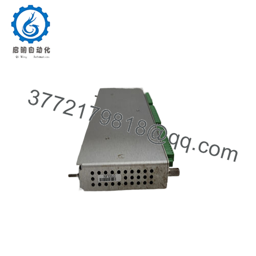
- Product Model: Bently 149992-01
- Product Brand / Series: Bently Nevada / 3500 System
- Module Type: 16-Channel Relay Output Module (3500/33 family)
- Key Features:
- Provides 16 programmable relay outputs, each with configurable logic and voting behavior
- Independently programmable “Alarm Drive Logic” per relay, using AND / OR logic, inputs like Alert / Danger / Not-OK / measured variables
- Typical power consumption ~5.8 W; standard full-height module with rear I/O module
- Relay contact life, arc suppression, and environmental sealing consistent with 3500/33 relay standards

- 149992-01
- 149992-01

Applications & System Context
In a Bently 3500 monitoring system, sensors, monitors, and communication modules provide diagnostic and protective data. But to act on alarms, integrate with external control systems, or drive shutdown devices (valves, breakers, annunciators), you need discrete relay outputs. The 3500/33 relay module is the standard way to implement those outputs, and 149992-01 is one of the module variants in that family.
You might see it in turbine, compressor, or generator protection racks: when a measured parameter (vibration, temperature, pressure) crosses a threshold, you need to drive a relay that signals a control system or triggers hardware. The 16-channel capacity means one module can serve many alarm points, reducing module count and wiring complexity.
In retrofit or expansion projects, replacing older external relay arrays or adding outputs is simplified using a 149992-01 inserted into the existing 3500 rack architecture.
Because the 3500/33 module logic is tightly integrated with the rack’s monitor logic and configuration software, deploying 149992-01 enables elegant coordination between internal diagnostics and external actuation.
Role, Integration & Architecture
The 149992-01 is a relay output logic module. In a 3500 rack:
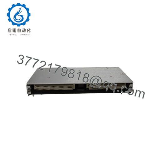
- It is installed in a full-height front slot, typically to the right of the Transient Data Interface (TDI) module or other monitor modules.
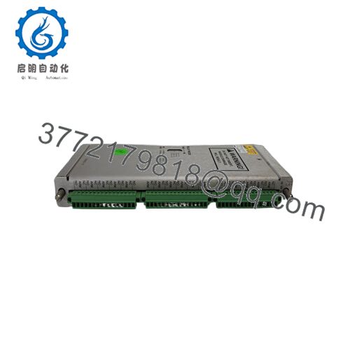
- A rear I/O module sits behind it (in the matching rear slot) to handle external wiring to contacts and field devices.
- Each of the 16 relays can be separately programmed using the 3500 Rack Configuration software. You can define which inputs (Alert, Danger, Not-OK status, measured variables) feed the logic for each relay.
- The module supports Alarm Drive Logic that uses AND / OR combinations of inputs. You can also apply voting behaviors or mixture logic per channel.
Because the 149992-01 basically extends the internal monitoring logic to external actuation, it is critical that its configuration and wiring match the project’s control logic requirements.
One caution: for Triple Modular Redundancy (TMR) systems, the standard 3500/33 relay modules (including 149992-01) are not used — instead, a dedicated 3500/34 TMR Relay Module is required.
Technical Features & Benefits
Let’s examine the specific technical features and advantages of 149992-01:
Sixteen Relay Outputs
With 16 output relays in one module, you get a high channel count per slot, enabling many alarm or control points without needing multiple modules.
Programmable Logic per Relay
Each relay’s logic can be curated: you can combine alert / danger statuses, “Not OK” signals, or measured variable thresholds using AND / OR logic. That flexibility reduces the need for external logic or control wiring.
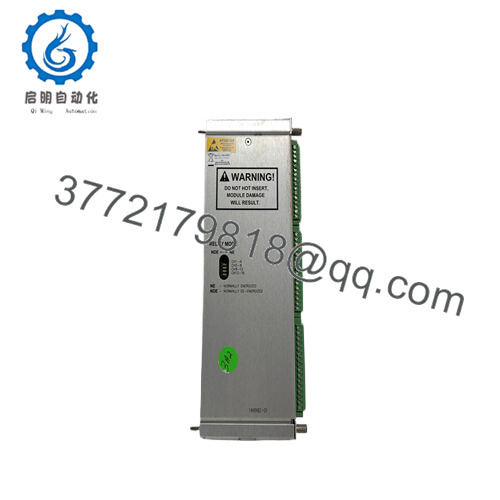
Selectable NO / NC (Normally De-energized / Energized)
Relays can be configured per channel as normally de-energized or normally energized, in groups of four channels.
Relays with Arc Suppression & Sealing
Each relay is epoxy-sealed and includes an arc suppressor (250 Vrms standard) to guard against switching transients.
Contact Life & Ratings
Typical contact life is specified around 100,000 cycles at 5 A, 24 Vdc or 240 Vac.
Modest Power Consumption
The module typically draws around 5.8 W under normal operation. That’s reasonable for a 16-relay module.
Front-Panel LED Indicators
Key LED indicators include:
- OK LED: module health / status
- TX/RX LED: communications with rack modules
- CH Alarm (Channel Alarm) LED: lights when a relay’s logic is in alarm state
These assist in commissioning and fault diagnosis.
Standard Mechanical & Environmental Design
Dimensions and weight match typical 3500/33 modules: ~241 mm × 24.4 mm × 242 mm, weight ~0.7 kg.
Operating temperature range is –30 °C to +65 °C, with storage –40 °C to +85 °C.
The module meets industrial EMC and safety requirements per the 3500 system specs.
Technical Specifications Table
Below is a spec table summarizing 149992-01, combining general 3500/33 module data and the known variant details:
| Parameter | Specification / Detail |
|---|---|
| Model / Part | Bently 149992-01 (3500/33 16-Channel Relay Module) |
| Module Type | Full-height relay logic module (paired with rear I/O module) |
| Relay Outputs | 16 independent relay outputs |
| Alarm Drive Logic | Programmable per relay (AND / OR model, combining Alert, Danger, Not-OK, measured variables) |
| Relay Type | SPDT (Single-pole, double-throw) ; epoxy sealed, arc suppressor 250 Vrms |
| Contact Life | ~100,000 cycles @ 5 A, 24 Vdc / 240 Vac |
| Power Consumption | ~5.8 W typical |
| Dimensions (Front Module) | 241 mm × 24.4 mm × 242 mm |
| Weight | ~0.7 kg / 1.6 lb |
| Rear I/O Module Dimensions | 241 mm × 24.4 mm × 99.1 mm (approx) |
| Operating Temp | –30 °C to +65 °C |
| Storage Temp | –40 °C to +85 °C |
| LED Indicators | OK, TX/RX, Channel Alarm |
| Relay Configuration | Four groups of 4 channels, selectable NO / NC operation per group |
| Voting / Logic Modes | Supports voting logic, AND/OR combinations, latching options |
| System Use | Normal (non-TMR) relay module; TMR systems use 3500/34 instead |
Installation & Maintenance Advice
Drawing on field experience and standard 3500/33 module practices, here are tips when installing or maintaining 149992-01:
Slot & Module Placement
Install 149992-01 in a full-height front slot (to the right side of the TDI or monitors). Be sure the rear I/O module behind it is aligned correctly. Incorrect placement or misalignment breaks communication or wiring.
Configuration & Logic Setup
Through the 3500 Rack Configuration software, configure each relay’s logic. Be deliberate: combine alert/danger, Not-OK, or direct measured variables according to your application. Avoid contradictory or looping logic.
Wiring Practices
Use proper gauge, shielded wiring where needed. Keep signal and power cables separated. Grounding practices matter to avoid noise in relay circuits.
LED Diagnostics
During commissioning, verify LED behavior:
- OK LED should indicate module health
- TX/RX LED should blink when communicating
- Channel Alarm LED should light when a particular relay logic is active
If any LED is off or erratic, check wiring, backplane connection, or configuration.
Load Testing
Before putting into service, test each relay under its actual expected load (voltage, current) and observe switching behavior. Confirm it handles switching transients without failure.
Thermal / Environmental Considerations
Ensure proper ventilation in the rack. The relay module’s components (coils, contacts) can be sensitive to temperature extremes or overheating.
Periodic Inspection
Over time, contacts, solder joints, or terminal integrity may degrade. Inspect for corrosion, loosening, or wear. Retighten or replace as necessary.
Spare Module Strategy
Keep a spare 149992-01 (same firmware / revision) preconfigured (if possible), so replacement in the field is straightforward and minimizes downtime.
Firmware / Version Compatibility
If Bently issues firmware updates to the 3500/33 series, ensure 149992-01 is compatible, back up logic configuration before upgrade, and re-test logic after upgrade.
TMR & Redundancy
If your rack is using TMR logic, do not use standard 3500/33 modules — use the dedicated 3500/34 TMR Relay Module instead.


