 WhatsApp: +86 16626708626
 Email:
  Phone: +86 16626708626
Description
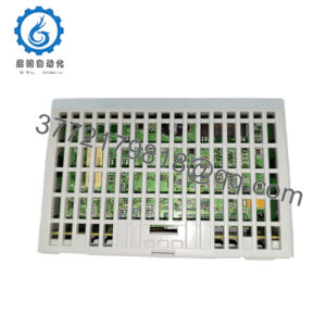
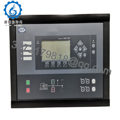
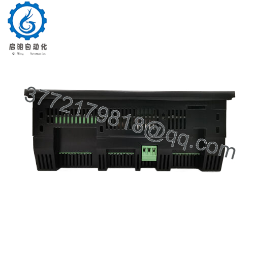
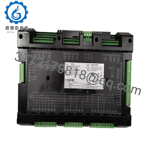
Product Model: AGC242 (DEIF AGC 242)
Product Brand: DEIF (Denmark)
Product Series: AGC-200 / Advanced Genset Controller
Key Features:
- Supports synchronisation, load sharing, multiple generators, and bus tie breakers in power plant setups (e.g. up to 16 gensets, 8 bus tie breakers)
- Multi-bus communication: CAN A/B/C, Modbus / RS-485, integrated power management logic
- Supports a wide range of generator/mains monitoring: voltage (100-690 V AC), current, frequency, protection functions
- Rugged design: supply 12/24 V DC input, operating temperature –25 °C to +70 °C (or wider in some sources)

- AGC242
Role & System Fit
The DEIF AGC242 is part of DEIF’s AGC-200 series of advanced generator (genset) controllers. These controllers are designed to manage, protect, and synchronise generator sets within both simple and complex power installations. The AGC242 is a mid-to-high capability variant that supports scenarios with multiple generators, load sharing, automatic mains failure (AMF), and advanced power management modes.
In a power plant or standby power system, the AGC242 acts as the brain: it measures generator voltage, current, frequency, mains parameters, and issues commands to control fuel / speed, synchronize breakers, manage loads, and execute safety / protection. It also interfaces with higher-level SCADA / monitoring via communications (CAN, Modbus). Because modern installations often combine multiple generators in parallel or grid-tie mode, controllers like the AGC242 are essential to orchestrate the interactions smoothly and safely.
Compared to simpler AMF controllers, the AGC242 is built for more complex plant operation—supporting many breakers, graphically configurable layouts, plant mode switching, and logging. It is used in installations ranging from backup power, island (off-grid) systems, to hybrid / microgrid environments.
Technical Features & Benefits
Communication & Network Features
- The AGC242 supports three CAN channels (CAN A, B, C) with galvanic separation, used for tasks such as load sharing, linking to external I/O modules, and power management coordination.
- It also supports Modbus (RS-485) for integration with SCADA or higher-level supervisory systems.
- The CAN “CANshare” feature enables fast digital load sharing with low latency, useful in parallel genset operation.
- Remote operator panels (e.g. AOP-2) can be connected via CAN to display alarms, values, control inputs, etc.
These features make AGC242 suitable for both standalone genset control and integrated multi-set plant control.
Measurement, Protection & Power Management
- The AGC242 measures voltage (mains / generator) in ranges typically from 100 to 690 V AC (line-to-line or phase) with galvanic separation.
- It monitors current on generator outputs and mains circuits and uses them for load calculations, overcurrent protection, and load sharing.
- Frequency measurement is supported (e.g. in typical 50/60 Hz systems) for synchronizing and control.
- Protective features: over/undervoltage, over/under frequency, reverse power, phase sequence, and more protection functions embedded in the controller.
- Power management modes: automatic mains failure (AMF), steady power mode, load takeover, power export, peak shaving, spinning reserve control. The AGC200 series supports these modes, and AGC242 is a variant in that line.
Because the controller integrates both measurement and control logic, fewer external modules are needed, reducing wiring and complexity.
Supply, Environmental & Interface
- According to vendor sources, the AGC242 can accept 12 V or 24 V DC supply (around 8 V to 30 V range).
- Operating temperature is often quoted as –25 °C to +70 °C in multiple sources.
- Dimensions and physical form factor vary across supplier listings; one listing cites 192 mm × 96 mm × 50 mm as one configuration.
- In some spec listings, for example from Shenzhen supplier, inputs include a wide operating range of AC voltage (15–500 V AC), current inputs, etc., and outputs like fuel control (10 A DC), start relay (16 A AC1), alarm outputs (5 A DC).
These features give the AGC242 flexibility in system design, allowing it to be used in many different generator / mains configurations.
Technical Specifications Table
Here is a spec table summarizing data gleaned from DEIF’s spec sheets and vendor sources. Use this as a guideline and always cross-check with your unit.
| Parameter | Value / Range | |
|---|---|---|
| Model | AGC242 (DEIF AGC 242) | |
| Product Type | Advanced Genset / Plant Controller | |
| Supply Voltage | 12 V or 24 V DC (typical) | |
| Input Voltage (AC) | 100 to 690 V AC (configurable) | |
| Current Input | 0.25–5 A AC (some spec) | |
| Frequency Range | 10–400 Hz | |
| Operating Temp | –25 °C to +70 °C | |
| CAN Communication | 3 Galvanically Isolated CAN channels | |
| Modbus / RS-485 | Yes | |
| Outputs (example) | Fuel control 10 A DC, Start relay 16 A AC1, Alarm 5 A DC | |
| Plant Modes | AMF, load sharing, peak shaving, power export | |
| Logging | Lifetime event and alarm logging (SD card) | |
| Protection Functions | Over/under voltage, over/under frequency, reverse power, phase loss |
Installation & Maintenance Insights
Here are practical guidelines, caveats, and tips for using AGC242 in the field.
Mounting & Environmental Considerations
- Mount the controller in a well-protected enclosure to avoid exposure to excessive moisture, dust, or mechanical shock.
- Allow clearance for airflow, wiring access, and heat dissipation—controllers handling multiple I/O and power measurements may generate heat.
- In harsh climates, ensure that the enclosure is rated for extremes (e.g. condensation protection, sealing) particularly since the AGC242 is used in field or engine room environments.
Power & Wiring
- Use a stable, regulated 12 V or 24 V DC supply with sufficient capacity (accounting for controller consumption plus any internal loads).
- For measuring AC generator / mains voltages and currents, ensure properly rated CTs (current transformers) and PTs / voltage dividers or measurement transformers.
- Keep measurement wiring separate from power wiring, and use shielded cables for analog or communication lines (CAN, RS-485) to reduce EMI and crosstalk.
Commissioning & Configuration
- Use DEIF’s configuration or service software (PC tool) to set measurement ranges, plant topology, breaker arrangements, interlock logic, and power management modes.
- Test synchronization, load-sharing, and protection functions during commissioning—simulate different load and breaker scenarios.
- Use the event logger and diagnostic tools integrated into AGC242 to validate operation and detect anomalies early.
Fault Handling & Replacement
- Monitor status bits, alarms, and fault registers. The controller logs events and alarms, which is helpful for post-mortem analysis.
- For replacement, ensure revision compatibility, backup configuration files, and test the replacement off-line where possible.
- Because the AGC242 can be part of redundant or multi-controller plant systems, ensure smooth switchover logic is in place if one unit fails or is replaced.