 WhatsApp: +86 16626708626
 Email:
  Phone: +86 16626708626
Description
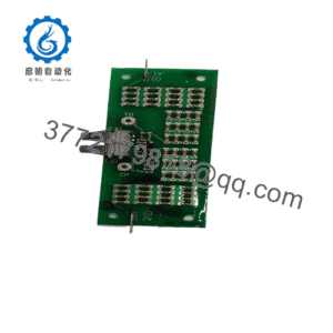
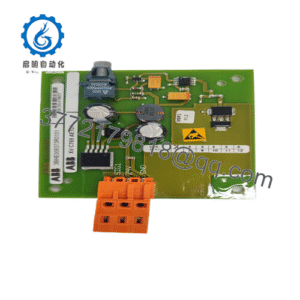
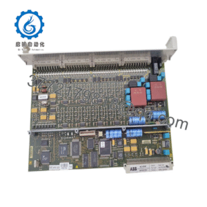
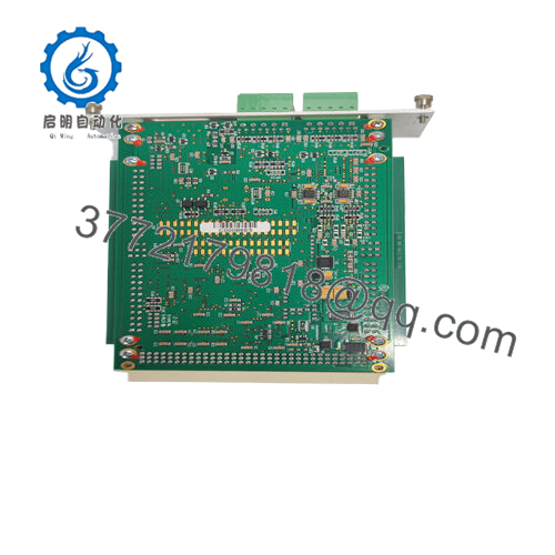
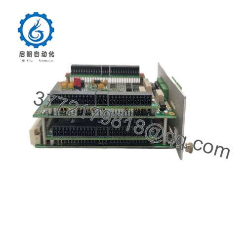
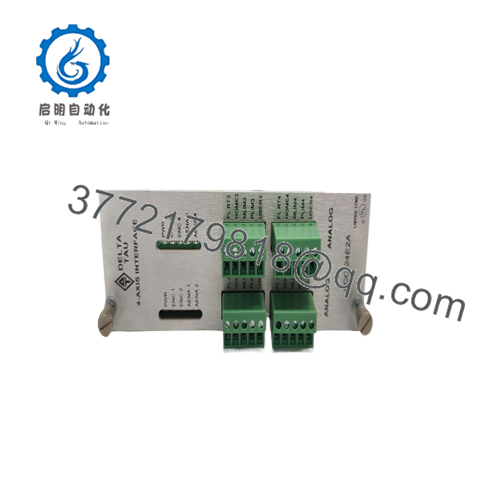
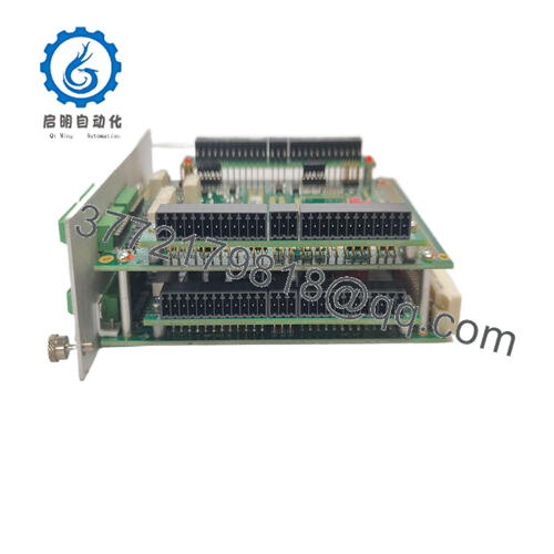
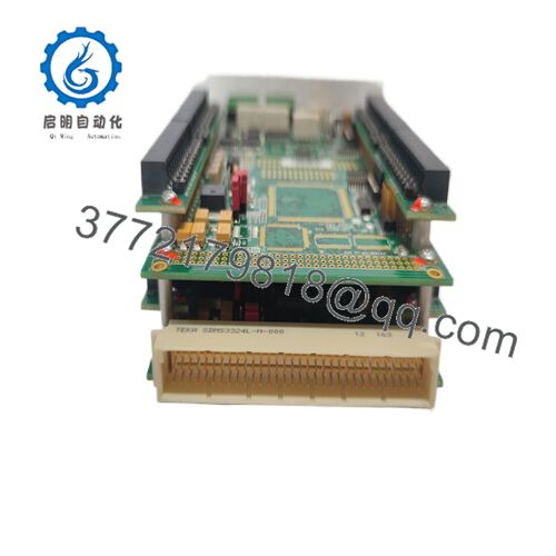
Product Model: ACC-24E2A
- Product Brand: Delta Tau
- Product Series: ACC-24E2 family (Axis Expansion Cards)
- Product Features:
• Provides 2 or 4 servo/stepper channels for UMAC/MACRO systems, with analog ±10 V or pulse-&-direction commands.
• Supports encoder inputs (differential/single-ended) and flag inputs/outputs for integrated motion feedback logic.
• Plug-in rack card (3U form) for UMAC/Turbo/MACRO backplane expansion — no onboard CPU, offloads interface functions.
• Flexible configuration via jumpers/DIP switches for mode, clock sourcing, external power, and encoder loss detection.
Applications & Industry Context
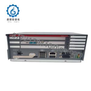
In sophisticated machine setups—whether high-precision CNC machines, multi-axis gantries, robotics platforms, or production automation lines—motion control systems often require more axes than the base controller card was designed for. That’s where the ACC-24E2A delivers value. It allows you to scale your servo/stepper axis count by adding expansion channels that integrate seamlessly with the host controller (such as a UMAC or MACRO station).
Consider a robotics cell where the base controller handles six axes. A future upgrade adds a tool-changer and vision-guided manipulator requiring two more axes of motion and encoder feedback. Rather than replacing the entire CPU, engineers can add an ACC-24E2A board to provide those additional axes, including encoder inputs, ±10 V analog torque or velocity outputs, and flag logic for limit switches or home sensors. Because the board sits on the existing backplane, it inherits the deterministic timing, motion-loop integration, and synchronization of the primary motion system.
In retrofit projects for legacy equipment, many systems still accept ±10 V velocity or torque commands and step/pulse signals rather than modern PWM. The ACC-24E2A supports both, making it a practical bridge between older drive paradigms and modern motion controllers. The board is also used in test benches or dynamic assemblies where synchronized channels with encoder feedback and flag logic are needed for high-accuracy, multi-axis coordination.
In short: when reliability, modular expansion and integration into a motion-controller ecosystem matter more than just raw axis count, the ACC-24E2A shines. It’s not for generic I/O, but for interface duties in motion systems where timing, feedback, and signal conditioning matter.
Product Role & System Fit
The ACC-24E2A acts as an axis expansion interface board—not as a motion CPU or a power amplifier—but as the logical connection between the controller’s servo/stepper architecture and the physical drive/feedback systems for added axes.
In system architecture terms: the main motion CPU executes trajectory calculations, interpolation, gantry logic, and coordination. Each axis typically has a servo card, driver/amplifier, motor and feedback loop. When you need additional axes, the ACC-24E2A is inserted into the expansion rack (via the UBUS or equivalent backplane) and presents up to four additional control channels (depending on Option 1A/1D). Each channel supports analog command output (±10 V), or pulse/dir output depending on mode. Encoder inputs, flags and compare outputs are provided to support high-performance motion loops.
The board’s internal connection is to the backplane: the motion CPU addresses its registers (via I- or M-variables) just like any other channel card, allowing seamless axis control, tuning and diagnostics. From a system integrator’s viewpoint, the ACC-24E2A is plug-and-play within the expansion infrastructure: you configure board address (via DIP switches), set jumpers for mode and clock sourcing, wire drives/feedback cables, and adapt the software variables accordingly.
Because the ACC-24E2A uses modes (analog ±10 V, pulse/dir, PWM) and supports both servo and stepper interfaces, it fits mixed-axis systems. For example, you could use one channel as a direct PWM for a drive, another as analog for torque control, and yet another for a stepper-based indexing axis—all on the same board, configured via hardware jumpers.
Integration tips: ensure the board is set to source or not source the phase/servo clocks depending on your system architecture. Also, pay attention to external +15 V or –15 V supply options if your specific setup demands analog isolation. The ACC-24E2A thereby becomes a flexible interface board within your motion system, helping you scale without reinventing the control architecture.

- ACC-24E2A
Technical Features & Benefits
The ACC-24E2A carries a number of technical features worth calling out—each tied to real benefits in motion systems:
Analog ±10 V & Pulse/Direction Command Support
The board supports ±10 V analog velocity or torque commands (typical for impedance or torque-control applications) and pulse/dir commands for stepper or simpler servo systems. This dual flexibility allows you to reuse drives or systems built on analog architectures while integrating into modern motion controllers.
Encoder Input Channels with Differential/Single-Ended Support
Each channel supports 3-channel encoder inputs (A/B/Z or Sin/Cos) either differential or single-ended. There is also encoder-loss detection circuitry, useful in high-safety or high-precision applications.
Flag Inputs/Outputs and Compare Outputs
For each channel the board provides eight input flags and two output flags, plus compare outputs for event capture. This means you can hook home/sensor limits directly, feed drive enables, and integrate compare-based motion events (such as camming or indexing) all on the same card interface.
Phase & Servo Clock Management
Proper servo timing demands correct clocking. The ACC-24E2A allows jumper configuration for phase/servo clock source (internal or external) and can auto-manage via firmware if you set jumper E13 to select auto on UMAC Turbo systems. That helps reduce clock conflicts and watchdog faults.
Modular Expansion – Option 1A/1D for 4-Axis
By default, the baseboard supports two axes (channels 1 & 2). If you order the Option 1A (or 1D) expansion piggy-back board, you get channels 3 & 4, effectively enabling up to four axes per card. That modular expansion helps in conserving rack slots and scaling efficiently.
Wide Input/Power Configuration Flexibility
Board runs from backplane supply (typically +5V, +15V, –15V). If you require analog isolation, you can jumper for external +15V and –15V supply, separating analog ground (AGND) from the digital ground plane (via jumpers E85/E87/E88). That is beneficial when the board is mounted near noisy power electronics.
Compact Form Factor & Backplane Plug-In
The card is 3U format, occupies one rack slot (or two with Option 1A), and plugs directly into the expansion backplane with standard UBUS pin header. This ensures tight integration and deterministic communication with the motion CPU.
From a practical standpoint, all these features translate into fewer separate interface modules, reduced wiring, integrated signal logic (limits, flags, compare), and consistent motion-controller interface mapping. The ACC-24E2A lets you treat additional axes as “native” to your motion architecture rather than aftermarket add-ons.
Technical Specifications Table
| Specification | Value / Description |
|---|---|
| Model | ACC-24E2A |
| Function | Axis expansion board (interface for 2 or 4 servo/stepper channels) |
| Command Output Modes | ±10 V analog (velocity/torque) or Pulse/Direction (stepper/servo) |
| Encoder Input Channels | Each channel: 3-wire (A/B/Z) encoder input, differential/single-ended |
| Flag IO | Each channel: eight input flags, two output flags |
| Axes Supported | 2 axes standard; up to 4 axes with Option 1A/1D upgrade |
| Clock Configuration | Phase & servo clock managed via jumper E13 (auto) or manual |
| Power Requirements | +5V @ ~0.55 A (base) / with Option1A ~0.95 A; ±15V support via backplane or external |
| Environmental | Operating Temp: 0 °C to 45 °C; Storage: –25 °C to 70 °C; Humidity: 10%–95% non-condensing |
| Dimensions | Length: 16.256 cm (6.4 in); Height: 10 cm (3.94 in) (base) |
| Mounting | Standard 3U rack card, plugs into expansion backplane (UMAC/Turbo/MACRO) |
Note: Always consult the full manufacturer manual for your exact variant and version before integration.
Installation & Maintenance Insights
From field experience with the ACC-24E2A, here are best-practices and tips for installation and upkeep:
Rack Slot & Board Insertion
Always power down the backplane before inserting or removing the card. Align the card carefully with the backplane connector — backplane pins can be fragile, and mis-seating can cause bad contacts or even system faults.
Jumper & DIP Switch Setup Pre-Power-Up
Before applying power, set jumpers such as E13 (clock auto/ manual), E85/E87/E88 (external vs backplane ±15 V supply), E1A/E2A etc. for stepper mode or analog mode. DIP switch S1 sets board address, so each ACC-24E2A must have a unique address. Scribd
Analog Ground Isolation
If you use analog ±10 V commands and your cabinet has high switching noise (drives, inverters), consider using an external ±15 V power supply to isolate AGND from the digital ground plane (jumper E85/E88). This helps reduce analog noise or ground-loop induced errors.
Wiring Best-Practices
- Command outputs (±10 V) should be routed using shielded twisted-pair, with the shield grounded at one end only.
- Encoder inputs: keep differential pairs twisted, and avoid routing near motor power cables.
- Flag input wires (limit switches, home sensors) should be properly debounced and shielded if long runs.
- Use termination resistor packs if you have long encoder cable runs; the ACC-24E2A provides resistor pack sockets for this purpose.
Clock & Timing Synchronization
When multiple ACC-24E2A boards are used, only one should source the phase/servo clocks; others must be configured as receivers. Incorrect clock settings can cause watchdog faults or asynchronous motion. Many newer UMAC Turbo firmware versions allow automatic clock selection if E13 is set accordingly.
Commissioning Steps
- After wiring, power the system and verify that the board is recognized (check base address mapping via I-variables such as I7200, I7300 etc.).
- Test channels one at a time: apply known ±10 V commands and verify the drive responds; swap to pulse/dir mode if used.
- Monitor encoder counts and flags in the motion controller software; ensure limit/home flags function as expected.
- Inspect board temperature after a few hours of operation; it should run at normal ambient—excess heat may indicate grounding or wiring issues.
Maintenance / Inspection
- Periodically (e.g., every 12-24 months) power down and reseat the card to ensure good contact under vibration or cabinet movement.
- Inspect connectors, jumpers, and wiring for any signs of wear, corrosion or loosening.
- Maintain backup of your configuration (jumper settings, DIP settings, I-variable map) so that if the board fails you can replace and restore quickly.
- If faults recur, review the fault/flag log in the motion controller—encoder loss detection circuits (supported by ACC-24E2A) often catch wiring or sensor failures before major motion disruption.
By following these steps, the ACC-24E2A will serve reliably as an integral expansion component of your motion control architecture.