
 WhatsApp: +86 16626708626
 Email:
  Phone: +86 16626708626
Description
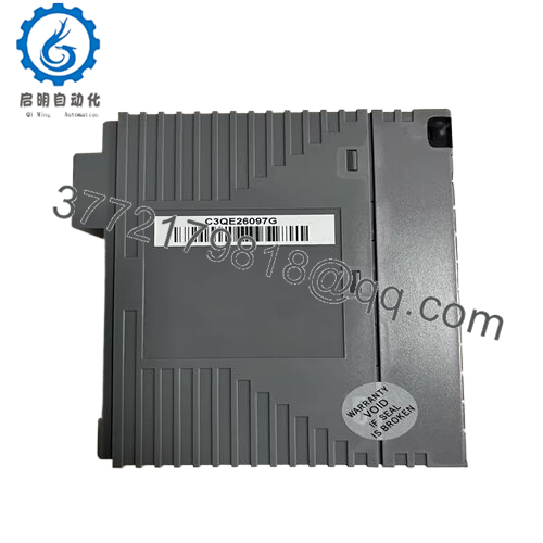
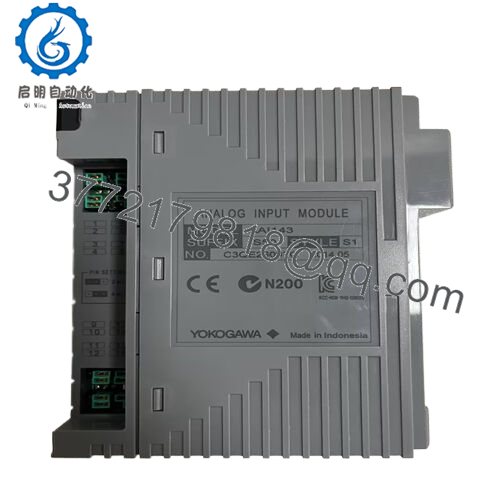
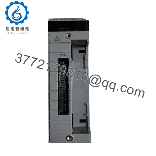
Product Model: AAI143-S50
Product Brand: Yokogawa
Product Series: AAI143 Analog Input Module
Product Features:
- 16 isolated input channels supporting 4–20 mA signals
- Input resistance ≈ 270 Ω at 20 mA, rising to ~350 Ω at 4 mA
- Fast update period (10 ms) and accuracy ±16 µA
- Supports dual-redundant configuration and HART communication options
Product Role & System Fit
The AAI143-S50 is an analog input module, typically used within Yokogawa’s DCS or process automation systems (e.g. CENTUM families or CS3000). It serves as the interface between field 4–20 mA transmitters (or voltage sources) and the control system, converting, isolating, and digitizing these analog signals so that controllers, SCADA, or operators can monitor and control processes.
Because it’s part of the AAI143 (Analog Input) family, this module is designed for isolated operation: each channel is galvanically isolated from the system side, reducing ground-loop interference and improving robustness in noisy industrial environments.
In a Yokogawa control rack or I/O shelf, the AAI143-S50 would typically plug into a carrier or chassis, connecting to field wiring on one side (terminals or connector blocks) and to the system bus or backplane on the other. Controllers or function block logic read process variables (pressure, flow, temperature, level) from this module. In many systems, the module also participates in dual-redundant configurations, meaning two AAI143 modules exist in parallel (odd/even slots) for higher system availability.
One distinguishing point: because the suffix is S50, this is a standard type without explosion protection (suffix “5” meaning “with no explosion protection”) and “0” indicating the basic variant. If you need versions with HART or intrinsic safety (for hazardous zones), there are alternate suffixes (e.g. “H” or “E”) in the Yokogawa AAI143 line.
Because the AAI143-S50 supports 16 channels, you can aggregate many field signals into one module, reducing rack footprint. Its design (input resistance, sampling time, isolation) makes it well-suited for real-time control loops, diagnostics, and high-reliability system architecture.

- AAI143-S50

Applications & Industry Context
In process plants (oil & gas, chemical, petrochemical, power generation, water & wastewater, pharmaceuticals), analog I/O modules like AAI143-S50 are indispensable. Consider a few realistic use cases:
- Pressure, flow, level, temperature sensors: Many process devices output 4–20 mA signals. The AAI143-S50 digitizes those inputs, isolates them, and forwards them to the DCS for control logic, alarming, or trend logging.
- Redundant systems: In safety-oriented or critical plants (e.g. power, petrochemical), dual AAI143 modules are often deployed. One is active; the other is standby. On fault or maintenance, the redundant module can seamlessly take over, ensuring no signal loss.
- Retrofits and expansions: In upgrades of older Yokogawa or hybrid control systems, the AAI143 family is often retained (or replaced with like variants) to preserve compatibility with field wiring, terminal blocks (e.g. ATA4S or ATK4A cable interfaces), and system diagnostics.
- HART-enabled instrumentation networks: Some variants support HART communication, enabling device diagnostics, calibration, or variable reading over the same line as the analog 4–20 mA signal.
- High-noise or long-distance loops: Because each channel is isolated, the module mitigates issues with ground loops, common-mode interference, or potential differences between sensor ground reference points—common in large plants or across long instrument runs.
In summary: AAI143-S50 is intended for demanding, multi-channel analog acquisition in process automation settings, especially where redundancy, isolation, and reliable analog performance are required.
Technical Specifications & Benefits
Here’s a deeper dive into how AAI143-S50 performs and what makes it valuable in real systems.
Signal Input & Resistance
Each input channel expects a 4–20 mA signal. The input resistance is specified as roughly 270 Ω at 20 mA and about 350 Ω at 4 mA when the module is powered on. When power is off, the input resistance rises dramatically (500 kΩ or greater) to minimize loading. This behavior allows safe disconnection, sensor testing, or loop checks without interference.
Throughput & Accuracy
The module updates its readings every 10 ms, which is fast enough for many control loops and diagnostic purposes. The specified accuracy is ±16 µA, which ensures reasonable precision in process measurements.Drift due to temperature change is about ±16 µA per 10 °C.
Because of these specs, the AAI143-S50 is capable of maintaining fidelity in tight control loops, trending, and alarm logic, even under moderate noise, drift, or signal degradation.
Isolation & Withstanding Voltage
One of the module’s key strengths is galvanic isolation between the input side (field wiring) and system side (control bus). The module is rated for 1,500 VAC for 1 minute between input and system side (insulation test voltage). This high withstanding voltage helps protect against surges, ground faults, or transients, which are common in industrial environments.
Power & Consumption
On the system/control side, typical current consumption is 230 mA at 5 V DC or 540 mA at 24 V DC (depending on module variant and system voltage). The module supports powering of 2-wire transmitters; the transmitter supply voltage must be between ~19.0 V and 25.5 V, with output current limited to 25 mA.
Each channel may be configured for 2-wire or 4-wire transmitter mode by setting pins per channel, allowing flexibility in connecting a wide variety of sensor types.
Communication & Redundancy
Certain versions of AAI143 support HART communication, enabling reading of additional device variables, diagnostics, or calibration parameters over the same 4–20 mA loop. Also, dual-redundant operation is possible: two modules (e.g. in adjacent odd/even slots) can be configured so that one is active, and the other stands by, providing fault tolerance.
Physical & Environmental
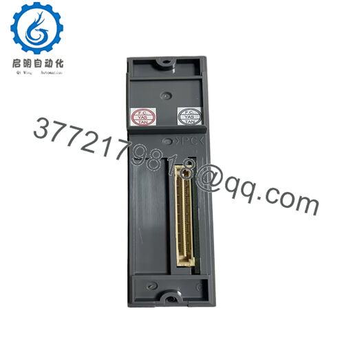
The module is relatively light (≈ 0.3 kg) and connects via terminal blocks, MIL connectors, or dedicated cables (e.g. KS1 cable) The module is mounted in a rack or I/O shelf within the control system, protected from humidity, dust, or chemical contamination.
Because it is of “standard” type (suffix “S50”), it does not provide explosion protection. For hazardous zones, one may need the “E” variant with intrinsic safety compliance.
Installation & Maintenance Insights
Getting optimal performance from AAI143-S50 in real systems depends on good wiring discipline, configuration, and maintenance. Here are best practices and tips from field experience:
Wiring & Grounding
- Use shielded, twisted-pair cable for analog signals. Terminate the shield only at one side to avoid ground loops.
- Ensure isolation barriers or proper earthing schemes are used if sensors or field devices are far apart or cross different ground potentials.
- Pay attention to terminal block wiring and cable dress to avoid mechanical strain or looseness, especially in vibration-prone installations.
Channel Configuration & Setup
- Configure each channel for 2-wire or 4-wire transmitter operation carefully (via setting pins). Mistakes lead to measurement errors or transmitter issues.
- If your system supports HART, verify that wiring and connectors allow communication—HART may require additional precautions (e.g. modulation path, capacitance)
- In dual-redundant setups, ensure modules are correctly aligned (odd-even slot pairing) and tested for failover behavior ahead of commissioning.
Commissioning & Testing
- After installation, perform loop checks by injecting known signals (4 mA, 12 mA, 20 mA) and confirm module readings.
- Monitor drift, noise, and stability over time, especially for long loops or noisy environments.
- Log baseline values, check for channel-to-channel consistency, and validate isolation via insulation tests (voltage withstand tests) as allowed by safety schedules.
Maintenance & Troubleshooting
- Periodically inspect connectors, cable integrity, and cleanliness of the I/O rack.
- Check for loose terminal screws, oxidation, or corrosion in humid or industrial environments.
- Monitor channel faults or discrepancies, and if a channel fails, swap modules or use redundant module features.
- When replacing modules, preserve channel mappings, calibration offsets, and parameter settings so that switchover is seamless.
Because the AAI143 family is mature and well-documented, repair or replacement modules (new, remanufactured, or used) are generally available. It’s wise to keep a spare module or two in inventory for mission-critical systems.
Related Models
Here are some other variants or modules in the Yokogawa AAI143 / analog input family, with key differences:
- AAI143-S00 – basic standard type (no explosion protection) variant
- AAI143-H50 – supports HART communication (digital overlay)
- AAI143-E50 – explosion-protected / intrinsically safe variant for hazardous zones
- AAI143-S50/K4A00 – same base module with KS cable interface adaptor (for connecting to terminal boards)
- AAI543 (analog output family) – output signal counterpart modules for analog outputs rather than inputs
These variants share much internal architecture, but differ in HART support, explosion rating, or terminal interface options.


