 WhatsApp: +86 16626708626
 Email:
  Phone: +86 16626708626
Description
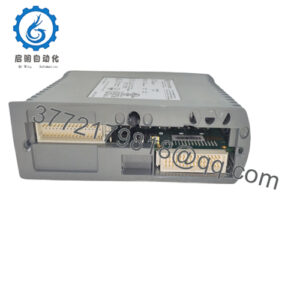
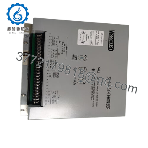
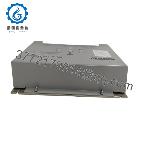
Product Model: 9907-028
Product Brand: Woodward
Product Series: SPM-A Synchronizer / 9907 Series
Product Features:
- Synchronizes generator to bus using ±10° phase window (no built-in voltage matching)
- Accepts 115/230 VAC input at 50/60 Hz; low internal power draw (≤ 5 W)
- Supports selectable dwell time (1/8, ¼, ½, 1 s) and multiple operating modes (OFF, RUN, CHECK, PERMISSIVE)
- Relay outputs for breaker closure (resistive & inductive ratings) and compatibility with Woodward load sharing or EPG systems

- 9907-028
Applications & Industry Context
In power generation, synchronization of a standby or auxiliary generator to an existing bus is critical to avoid damaging currents or mechanical stress. The 9907-028 is designed precisely for that role—it acts as a synchronizer unit, monitoring the phase and frequency of a candidate generator and the system bus, and when conditions align, commanding breaker closure.
You’ll find the 9907-028 in switchgear panels, genset control rooms, industrial plants, or standby power installations. In retrofit projects, this module is often installed when a plant upgrades from manual paralleling to automatic synchronization. Because it supports both 115 VAC and 230 VAC inputs, it can adapt to many facility power systems.
In oil & gas, municipal utilities, data centers, or critical infrastructure where multiple generators must run in parallel seamlessly, a synchronizer like the 9907-028 is often the gatekeeper: allowing only “in-phase” generators to close into the bus under safe conditions. Field engineers appreciate its selectable dwell time (delay before breaker command) and operational modes (RUN, CHECK, PERMISSIVE) for flexibility during commissioning or testing.
Because it does not include built-in voltage matching (in this variant), it’s best suited when your system already ensures voltage alignment or uses complementary equipment to adjust generator voltage.
Product Role & System Integration
The 9907-028 is a synchronizer control module (Woodward SPM-A family). Its core job: compare the generator’s voltage wave (phase and frequency) with the bus voltage, detect when they are within an acceptable phase window, and then command a breaker closure signal.
To achieve that, it has two voltage inputs—one from the generator, one from the bus (or utility). These pass through signal conditioners and phase detectors. The module internally compares the signals and, once phase difference falls within ±10°, it allows a command to close the generator breaker.
Internally, the module supports switchable dwell times (how long the alignment must persist before issuing the command) of 1/8, ¼, ½, or 1 second. The factory default is usually ½ second.
There is a user-installed mode switch (wired via external contacts) that allows four modes: OFF, RUN, CHECK, and PERMISSIVE. In RUN, it operates normally and can issue the breaker close; in CHECK, it synchronizes but will not command closure; PERMISSIVE performs checks but does not affect speed or voltage; OFF disables the synchronizer.
It provides relay contacts for breaker closure; in resistive mode, the contacts are rated at 10 A at 28 VDC or 3 A at 120 VAC; for inductive loads, 6 A at 28 VDC or 2 A at 120 VAC. The closure command is approximately 1 second in duration.
The 9907-028 is compatible with typical Woodward systems: 2301 series, EPG, 2500, and Load Sharing controls. It offers both high-impedance or low-impedance outputs depending on system needs.
Because of its modularity and mature design, the 9907-028 is often paired with breaker logic, load sharing controllers, and protective relays in a power control rack.
Technical Features & Benefits
Let’s dig deeper into what the 9907-028 brings to a paralleling setup.
Selectable Phase Window & Dwell Time
The ±10° phase matching window (standard on 9907-028) ensures that synchronization is only allowed when phase error is minimal. Dwell time options let you tune how tolerant or strict the system is. That gives you flexibility during system tuning or in noisy grids.
Low Power Consumption
The module is efficient—drawing up to 5 W under normal operation. That makes it easy to power from auxiliary AC sources or small control transformers.
Dual Voltage Input (115 / 230 VAC)
It supports both 115 VAC and 230 VAC supply inputs (50/60 Hz), making it adaptable to facility standards.
Flexible Operating Modes
The OFF mode disables it entirely (useful during maintenance). CHECK mode lets you test synchronization without exercising breaker commands. PERMISSIVE allows evaluation under conditions only. RUN is normal operation. This flexibility helps during commissioning or fault handling.
Relay Outputs with Adequate Ratings
Its breaker close relay is robust: capable of switching both resistive and inductive loads within specified limits, and providing 1-second closure pulses. These capabilities are well suited for driving auxiliary circuits or breaker coils.
Integration with Woodward Ecosystem
Because the 9907-028 is from the SPM-A series, it interfaces nicely with Woodward load sharing controls (2301, 2500, EPG). This compatibility simplifies system design and retrofit.
Rugged Operating Range
It is rated for operation from –45 °C to +70 °C, making it suitable for many industrial climates.
From a field perspective, engineers often mention that the predictability of the dwell timing and the simple mode switching make the 9907-028 easy to commission and tune. Its proven reliability in legacy installations also gives confidence when replacing older synchronizers.
Installation & Maintenance Insights
Here are practical tips from field experience and the official manual to help you install or maintain 9907-028 properly.
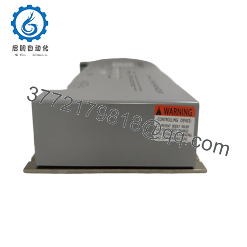
Mounting & Location
Mount the module in or near the switchgear or control cabinet. Ensure minimal interference from magnetic fields, and avoid mounting near heat sources. Use the specified mounting bracket or fixture so that wiring strain is minimized.
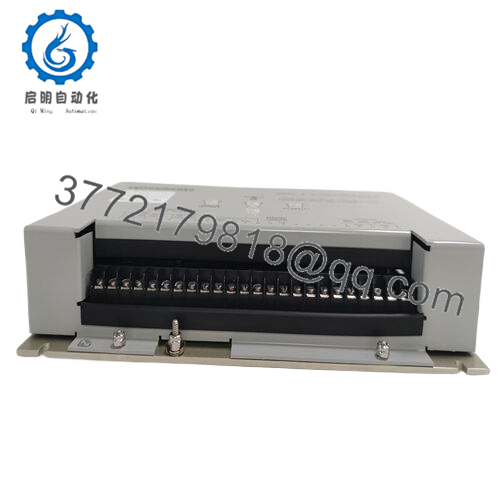
Voltage Input Wiring
Ensure the 115/230 VAC input is clean, stable, and within the ±10% tolerance range. Use proper fusing, transient protection, and wire gauge to minimize voltage drop or noise.
Signal Wiring & Polarity
Run separate, shielded cables for generator and bus voltage inputs. Follow correct phasing and ensure transformers, if present, are consistent. The phase offset potentiometer (factory adjusted) may need recalibration if transformer phase shifts are introduced.
Mode Switch Wiring
Connect the external 4-position mode switch (OFF, RUN, CHECK, PERMISSIVE) using contacts to terminals 10–13 (as per the wiring diagram). Ensure clear labeling so operators don’t unintentionally flip modes.
Commissioning Steps
- Begin in CHECK mode to observe synchronization behavior without letting closure occur
- Adjust dwell time and phase window until stable, repeatable alignment is seen
- Switch to RUN mode and validate that breaker closure command engages only when conditions are within limits
- Test in PERMISSIVE mode (logic check) to ensure all inputs and conditions are satisfied
- Cycle OFF and RUN to validate automatic reset behavior
- Monitor phase/frequency deviations under load transitions
Routine Maintenance
- Inspect terminals periodically for tightness and corrosion
- Clean internal components if dust accumulates
- Verify that mode switch and wiring remain intact
- Keep logs or records of dwell time settings, phase offset adjustments, and fault events
- Keep a spare 9907-028 or module part of stock to reduce downtime in case of failure
Handling & ESD Precautions
When handling or replacing, follow ESD precautions and avoid touching internal circuitry. Cap connectors and use antistatic packaging if removed from the cabinet.
Because it’s a mature product, failures are often due to terminal corrosion, relay fatigue, or degraded signal paths—so maintaining clean connections greatly increases longevity.
Technical Specifications Table
| Parameter | Value / Description |
|---|---|
| Module Type | SPM-A Synchronizer Control (9907-028) |
| Input Voltage | 115 / 230 VAC (50/60 Hz) |
| Power Consumption | ≤ 5 W |
| Frequency | 50 / 60 Hz operation |
| Phase Matching Window | ±10° (standard) |
| Dwell Time Options | 1/8, ¼, ½, 1 s (factory default: ½ s) |
| Mode Selections | OFF, RUN, CHECK, PERMISSIVE |
| Breaker Close Relay | Resistive: 10 A @ 28 VDC, 3 A @ 120 VAC; Inductive: 6 A @ 28 VDC, 2 A @ 120 VAC |
| Breaker Command Duration | ~1 s |
| Operating Temperature | –45 °C to +70 °C (–49 to +158 °F) |
| Mounting Location | Switchgear or control panel mounting |
| Phase Offset Adjustment | Internal potentiometer for compensating transformer phase errors |
| Reset Behavior | Automatic lockout reset when phase error exceeds window after disconnection |
Related Models & Variants
Here’s a short list of sibling or variant modules you may encounter, or consider as alternatives:
- 9907-029 — variant with ±10° phase angle and 1% voltage matching capability (in contrast to 9907-028’s “no voltage matching”)
- 9905-001 — earlier variant in the SPM-A family, same ±10° but different internal options
- Other SPM-A variants (9905-002, 003, etc.) — with different phase windows or voltage matching options
- Modern synchronizer modules — newer digital paralleling controllers that combine voltage matching, load share, and networked communications
- Woodward Load Sharing / Synchronization control units (e.g. 2301, EPG) — these may offer built-in synchronization capabilities or interfaces to work alongside the 9907-028
If you plan a modernization, consider whether the 9907-028 still meets future needs for digital communication or advanced control, or whether migrating to a newer synchronizer is wise.