 WhatsApp: +86 16626708626
 Email:
  Phone: +86 16626708626
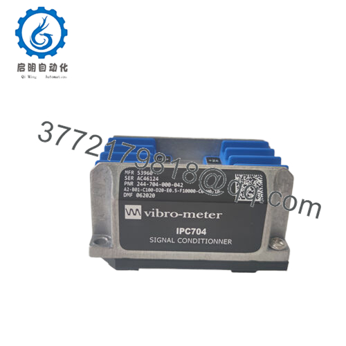
Description
Part Number Decoding
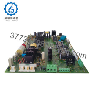
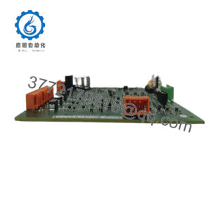
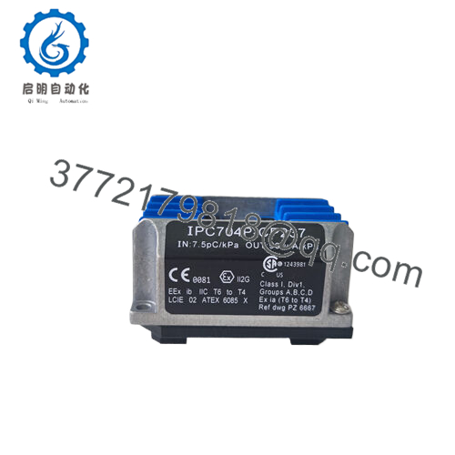
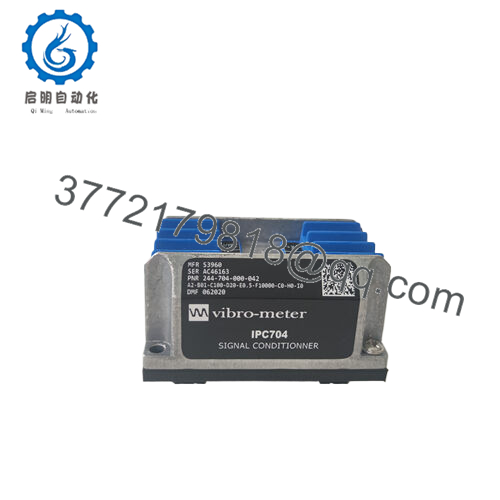
The string 244-704-000-042-A2-B01-C100-D20-E0.5-F10000-C0-H0-I0 is a Vibro-Meter configuration code for a VM600 module, likely an MPC4 (Machinery Protection Card) or a derivative, tailored for specific sensor inputs, signal conditioning, and monitoring tasks. Vibro-Meter’s modular nomenclature defines hardware and software settings. Here’s a breakdown based on standard Vibro-Meter conventions:
- 244-704-000-042: Base model identifier for the VM600 series card, likely an MPC4 variant with specific firmware or hardware revisions (e.g., Rev. 042).
- A2: Hardware configuration, possibly indicating a dual-channel setup for vibration inputs (e.g., accelerometers or proximity probes).
- B01: Sensor interface type, likely specifying compatibility with eddy-current probes or piezoelectric accelerometers, with standard gain settings.
- C100: Input range or sensitivity, potentially 100 mV/g for accelerometer inputs or a specific scaling factor for probe signals.
- D20: Measurement range, possibly indicating a 20 mm/s vibration velocity range or displacement limit for monitoring.
- E0.5: Integration time constant or filter setting, likely a 0.5-second response for smoothing vibration data.
- F10000: Sampling frequency or bandwidth, possibly 10 kHz for high-frequency detection of bearing faults or blade pass events.
- C0: Output configuration, indicating no additional analog outputs or specific relay setups.
- H0: No external hardware options, such as additional communication interfaces.
- I0: No special software or firmware customizations, using standard VM600 monitoring logic.
This configuration suggests a highly specialized module for monitoring vibration parameters like displacement, velocity, or acceleration, with tailored sensor compatibility and signal processing for critical machinery protection in SIL-rated environments.

- 244-704-000-042-A2-B01-C100-D20-E0.5-F10000-C0-H0-I0
Role in Industrial Automation
In the context of industrial automation, where real-time condition monitoring prevents equipment failures that could halt production or compromise safety, the Vibro-Meter 244-704-000-042-A2-B01-C100-D20-E0.5-F10000-C0-H0-I0 addresses challenges like undetected bearing wear, rotor imbalances, or transient shocks that traditional I/O modules might miss. Its role is to acquire high-fidelity vibration data from field sensors, process it with onboard algorithms, and relay alarms or trends to higher-level PLCs or SCADA systems, ensuring high reliability for process control in demanding applications. For instance, in a gas turbine, this module might detect early cavitation in bearings, triggering an alarm to prevent rotor damage, thereby maintaining critical system uptime and avoiding millions in repair costs.
The module excels in scenarios requiring modular integration, such as turbine-generator sets or centrifugal compressors, where its dual-channel inputs handle multiple sensor types (e.g., proximity probes for shaft position, accelerometers for casing vibration) without external conditioners. By embedding diagnostic algorithms like FFT analysis or peak detection, it offloads processing from the host controller, aligning with goals of streamlined data handling and reduced latency. In harsh environments with EMI or thermal extremes, its galvanic isolation and robust signal conditioning prevent noise-induced false positives, ensuring I/O signal accuracy. Keywords like “industrial automation,” “process control,” “I/O signal,” and “high reliability” are central—the Vibro-Meter 244-704-000-042 transforms raw vibration into actionable insights, enhancing predictive maintenance and safety compliance in setups where machine health is paramount.
Technical Positioning and Operation
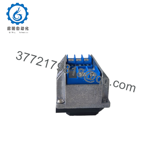
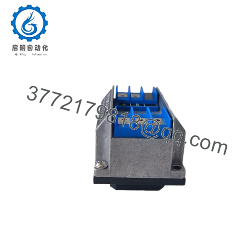
The Vibro-Meter 244-704-000-042-A2-B01-C100-D20-E0.5-F10000-C0-H0-I0 slots into a VM600 19-inch rack (e.g., ABE040 or ABE042), typically paired with a CPUM (Central Processing Unit Module) for communication and alarm logic, forming the core of a distributed condition monitoring system. Positioned in the signal acquisition and protection layer of the automation stack, it interfaces with field sensors via screw terminals or BNC connectors, conditioning inputs like 4-20 mA or millivolt signals from proximity probes (e.g., TQ402) or accelerometers (e.g., CA202). The module processes data locally, applying filters (0.5 s time constant) and sampling at 10 kHz to capture high-frequency events, then outputs processed values or alarms via the VM600 bus to Modbus TCP, Profibus, or relay outputs for integration with PLCs like ControlLogix or B&R systems.
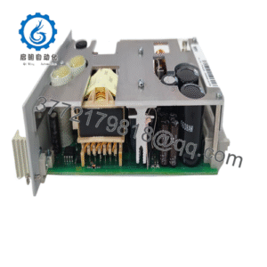
In a typical setup, the module supports dual-channel monitoring, where each channel independently tracks vibration metrics (e.g., 20 mm/s velocity, 100 mV/g sensitivity) with cold-junction compensation for thermocouple inputs if applicable. It integrates with software like VibroSight for configuration and trending, where diagnostic LEDs and bus-reported status flags alert on sensor faults or threshold breaches (e.g., Alert/Danger levels per ISO 10816). For example, in a steam turbine, the module might sample shaft eccentricity and casing vibration, applying FFT to detect misalignment harmonics, with alarms triggering shutdowns if levels exceed 20 mm/s—all while isolating channels to prevent crosstalk in noisy grids. Its compatibility with Vibro-Meter’s RPS6U power supply ensures stable operation, and the rack-based design supports hot-swapping for maintenance without disrupting other cards, minimizing wiring and enhancing scalability in process control architectures.
| Specification | Details |
|---|---|
| Model Number | 244-704-000-042-A2-B01-C100-D20-E0.5-F10000-C0-H0-I0 |
| Brand | Vibro-Meter (Meggitt Sensing Systems) |
| Type | VM600 Vibration Monitoring Module (MPC4 variant) |
| Input Voltage | 24 VDC (via VM600 rack PSU, 18-32 VDC range) |
| Operating Temp Range | -25 to +65°C |
| Mounting Style | 19-inch rack (VM600 ABE040/042) |
| Dimensions | 100 x 160 x 20 mm (Eurocard) |
| Weight | 0.3 kg |
| Interface/Bus | VM600 bus, screw/BNC terminals |
| Compliance | CE, ATEX Zone 2, IEC 61508 (SIL 2 capable) |
| Supported Protocols | Modbus TCP, Profibus DP (via CPUM) |
| Typical Power Draw | 5 W |
Key Benefits and Applications
Choosing the Vibro-Meter 244-704-000-042-A2-B01-C100-D20-E0.5-F10000-C0-H0-I0 equips your system with a vibration monitor engineered for relentless precision, where its high-frequency 10 kHz sampling ensures long-term performance by detecting transient spikes that could signal early bearing wear, allowing preemptive repairs that extend MTBF beyond 50,000 hours. In practice, this means turbines maintaining balance within 0.1 mm/s RMS, averting unplanned outages and slashing maintenance costs by up to 30% through predictive scheduling—crucial for processes where downtime compounds into revenue losses or safety risks.
The module’s modular integration streamlines deployments, as its plug-and-play rack design and VibroSight software reduce commissioning time by hours, enabling quick sensor additions without custom wiring. Maintenance is equally lean: diagnostic LEDs and bus alerts pinpoint channel faults, with hot-swappable cards supporting swaps under 10 minutes, aligning with strategies for sub-hour MTTR in uptime-critical sites. For facilities balancing legacy assets with modern analytics, this module transforms vibration data into a strategic asset, supporting high reliability and compliance with standards like API 670 without escalating rack space.
- Power Generation: Monitors turbine shaft vibrations in coal plants, using proximity probes to detect 20 mm/s excursions amid coal dust and 50°C ambients—ensures high reliability for process control, maintaining critical system uptime via early imbalance alerts.
- Oil and Gas: Tracks compressor casing vibrations in offshore platforms, with ATEX Zone 2 compliance and 100 mV/g sensitivity for accelerometers—upholds process control precision, preventing cavitation-induced failures in volatile atmospheres.
- Aerospace Testing: Measures test rig vibrations in jet engine stands, sampling at 10 kHz to capture blade-pass frequencies—delivers high reliability, ensuring I/O signal accuracy for fatigue analysis in high-vibration setups.
Related Components
- Vibro-Meter MPC4: Standard protection card for similar vibration tasks in VM600 racks.
- Vibro-Meter CPUM: Central processing module for Modbus/Profibus integration with 244-704-000-042.
- Vibro-Meter TQ402: Proximity probe for shaft displacement inputs to the module.
- Vibro-Meter CA202: Piezoelectric accelerometer for high-frequency casing measurements.
- Vibro-Meter RPS6U: Rack power supply for stable 24 VDC feeds to the module.
- Vibro-Meter IOC4T: Input/output card for relay outputs paired with MPC4 monitoring.
- Vibro-Meter ABE040: 19-inch rack chassis for housing multiple 244-704-000-042 modules.
Installation and Maintenance
Before Installation:
- Verify rack compatibility (ABE040/042) and firmware alignment via VibroSight (v10 or later) to avoid bus mismatches.
- Confirm sensor wiring (e.g., TQ402 probes) with a loop tester for <0.5 ohm resistance to ensure signal fidelity.
- Check 24 VDC supply ripple under 100 mV via oscilloscope, and torque terminals to 0.6 Nm for vibration resistance.
- In ATEX zones, apply Zone 2 labels and ground rack to <0.1 ohm per IEC 60079-14.
- Baseline input ranges with a calibrator (e.g., 100 mV/g, 20 mm/s) to validate C100/D20 settings.
Maintenance:
- Monthly: Check LEDs for green OK status; pull fault logs via VibroSight if alarms flash—reset transient errors via software.
- Quarterly: Inspect terminal contacts for corrosion in humid zones, cleaning with isopropyl; verify channel isolation >500 V with a megger.
- Annually: Simulate vibration spikes with a shaker table to confirm alarm thresholds under 200 ms response, offline to avoid false trips.
- These API 670-aligned routines ensure high reliability without rack downtime.