 WhatsApp: +86 16626708626
 Email:
  Phone: +86 16626708626
Description
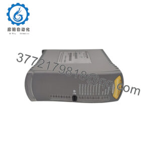
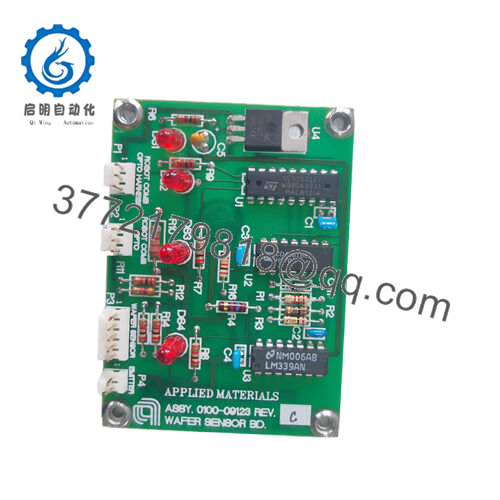
Product Model: 0100-09123
Product Brand: AMAT (Applied Materials)
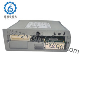
Product Series / Function: Wafer Sensor Board / Interface Module
Product Features:
- Ethernet interface for integration with tool control systems
- 24 V DC supply, low power consumption (~5 W)
- High-precision sensing (wafer temperature or related process parameter)
- Rugged construction to withstand semiconductor process environment
Applications & Industry Context
In semiconductor manufacturing, control and monitoring of wafer conditions (especially temperature, pressure, gas composition, etc.) is critical. The 0100-09123 wafer sensor board is used inside advanced process tools to monitor and relay sensor data to the tool’s control system. For instance, in diffusion, annealing, or etch modules, this board might read wafer temperature sensors, heater element feedback, or chamber condition sensors, then output those readings over Ethernet or internal bus lines to the higher-level system. It ensures that process stability is maintained and drift is detected early.
Because environmental tolerance is challenging in tools (heat, vacuum, chemical exposure), boards like 0100-09123 must be built robustly, with noise immunity, isolation, and stable signal conditioning. In upgrade or repair cases, this board is often replaced as a modular unit to restore tool functionality.
Product Role & System Fit
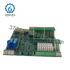
The 0100-09123 acts as a sensor interface / conditioning board. It sits between raw physical sensors (thermocouples, RTDs, wafer thermometry sensors) and the control system (e.g. the tool logic PLC or embedded controller). It performs amplification, filtering, perhaps calibration compensation, and then outputs processed data over Ethernet or a digital interface.
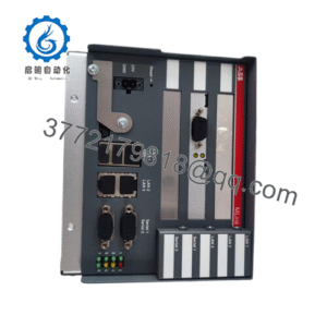
In many system architectures, 0100-09123 is co-located in the tool’s electronics cabinet or sensor housing. It interfaces to the tool’s main controller or process module via Ethernet or internal bus. Because it is sensor-facing, it must manage analog noise, grounding, and reliable signal paths.
In tool maintenance or module swaps, this board is often a common replacement part. An engineer replacing a failing sensor board often pre-configures it in lab conditions before swapping in the field, minimizing downtime.

- 0100-09123
Technical Features & Benefits
Here are the likely features and advantages, inferred from product listings:
- Ethernet Interface & Communication: One distributor listing describes it as having an Ethernet interface, facilitating integration into tool networks.
- 24 V DC Power Supply: The board is listed as operating from 24 V DC.
- Low Power (~5 W): The board draws relatively low power (≈ 5 W).
- Dimensions & Form Factor: One listing states dimensions of 200 mm × 200 mm × 20 mm, which suggests a square, planar board form.
- Environmental Tolerance: The product listing proclaims it is durable enough for semiconductor process environments (high temperature, vibration, etc.)
From a benefits perspective:
- Because the board handles sensor conditioning, it localizes noise suppression and calibration in one module. That reduces wiring complexity and improves signal fidelity.
- If a sensor path degrades (e.g. drift, open circuit), the board can report diagnostics or be swapped out as a single unit.
- Ethernet connectivity means fewer proprietary wires and easier downstream integration.
- Low power and compact design help in space-constrained tool electronics racks.
- Standardization of this board as a spare part accelerates tool servicing and reduces mean time to repair.
Technical Specifications Table
Below is a speculative / partly confirmed spec table based on available listing data. You should confirm each entry with original manufacturer documentation before usage.
| Parameter | Value / Range | Notes / Source |
|---|---|---|
| Interface | Ethernet | Listed in product description “Interface: Ethernet” |
| Supply Voltage | 24 V DC | As per listing |
| Power Consumption | ~5 W | As per listing |
| Dimensions | 200 mm × 200 mm × 20 mm | As per listing |
| Operating Temperature | 0 °C to +50 °C | One listing gives this range |
| Compliance / Standards | SEMI S2, IEC 60068-2-6, IEC 60068-2-7 | Cited on listing |
| Function | Wafer sensor board / measurement interface | From listing description |
| Signal Types | Wafer temperature and related sensors | Inferred from “wafer sensor board” listing |
Because public detail is limited, many internal specs like ADC resolution, isolation, channel count, noise floor, etc., are not listed in the public listing.
Installation & Maintenance Insights
Here are practical considerations and field tips for deploying 0100-09123:
- Mounting & Orientation: Mount it in its designated slot or enclosure inside the tool’s electronics cabinet. Pay attention to airflow and heat, ensuring components stay within rated temperature.
- Power Wiring: Use clean 24 V DC supply lines, with proper filtering, overcurrent protection, and decoupling to prevent noise injection. Verify polarity before powering.
- Ethernet / Network Wiring: Use shielded Ethernet cables, proper grounding, and avoid running them alongside high-power lines. Terminate cable ends properly and manage stray loops.
- Sensor Interface Wiring: For sensor leads (thermocouples, RTDs, etc.), use twisted-pair, shielded wiring, and single-end grounding of shields to prevent ground loops.
- Commissioning Testing: Before integrating into the tool logic, verify each sensor channel’s response, linearity, calibration, and noise behavior. Use known reference sensors to calibrate.
- Diagnostics & Monitoring: Monitor output stability, drift, error flags, and network communication health. If performance degrades, consider replacing the board before sensors or system logic.
- Spare Strategy: Keep a warm spare 0100-09123 in your inventory. Pre-test and calibrate it so it can be swapped quickly in the event of a failure.
- Periodic Inspection: Inspect connectors, solder joints, wiring integrity, and shielding at scheduled maintenance windows. Slight corrosion, dust, or connector looseness can degrade signal fidelity over time.
- Firmware / Configuration Backup: If the board uses firmware or has calibration registers, maintain backups so replacement is seamless.
In my experience working with semiconductor tool electronics, swapping a conditioned sensor board often recovers the tool faster than tracing out individual sensor wires—especially in tightly packed tool cabinets. Having reliable wiring and a tested spare is invaluable.